Idea Statica
  • Steel
  • Concrete
  • BIM & Workflows
  • Support & Learning
  • Pricing
  • Company
  • Steel overview
  • Connection design
  • Member design
  • Parametric design
  • Steel case studies
  • Concrete overview
  • Walls and D-regions
  • Anchoring design
  • Concrete case studies
  • BIM Overview
  • Supported integrations
  • Checkbot
  • Viewer
  • APIs
  • Support Center
  • E-learning & certification
  • Blog
  • Downloads & Licensing
  • Plans
  • Free community tool
  • Enterprise customers
  • Students & educators
  • How much will you save?
  • About us
  • Contact
  • Research & development
  • Authorized resellers
  • Meet our customers
  • Career
  • Steel
    Steel overviewConnection designMember designParametric designSteel case studies
  • Concrete
    Concrete overviewWalls and D-regionsAnchoring designConcrete case studies
  • BIM & Workflows
    BIM OverviewSupported integrationsCheckbotViewerAPIs
  • Support & Learning
    Support CenterE-learning & certificationBlogDownloads & Licensing
  • Pricing
    PlansFree community toolEnterprise customersStudents & educatorsHow much will you save?
  • Company
    About usContactResearch & developmentAuthorized resellersMeet our customersCareer
14-Day Trial
14-Day Trial

Subscribe to our newsletter

Company

  • About us
  • Partners
  • Careers
  • Patent

Resources

  • Customer projects
  • Case studies
  • Connection Library
  • Verification books

Legal

  • EULA
  • Global privacy policy
  • California Privacy
  • TOS Viewer
  • Licensing

Help

  • Contact
  • Quote request
  • Resellers
  • Downloads
FacebookInstagramLinkedInYouTube

© IDEA StatiCa 2009-2026

Trusted and used worldwide by engineers, fabricators & consultants.

Support CenterKnowledge Base Articles4.1 Material models (EN)
4.1 Material models (EN)
ConcreteKnowledge baseDetail 2DEN (Eurocode)Cracks

4.1 Material models (EN)

This article is also available in
ENCZDEESFRITPTNLHUROKRPLTHTRVIZH

Concrete - ULS

The concrete model implemented in the CSFM is based on the uniaxial compression constitutive laws prescribed by EN 1992-1-1 for the design of cross-sections, which only depend on compressive strength. The parabola-rectangle diagram specified in EN 1992-1-1 Cl. 3.1.7 (1) (Fig. 24a) is used by default in the CSFM, but designers can also choose a more simplified elastic ideal plastic relationship according to EN 1992-1-1 Cl. 3.1.7 (2) (Fig. 24b). The tensile strength is neglected, as it is in classic reinforced concrete design.

Fig. 26	The stress-strain diagrams of concrete for ULS: a) parabola-rectangle diagram; b) bilinear diagram.

Fig. 24The stress-strain diagrams of concrete for ULS: a) parabola-rectangle diagram; b) bilinear diagram.\textsf{\textit{\footnotesize{Fig. 24\qquad The stress-strain diagrams of concrete for ULS: a) parabola-rectangle diagram; b) bilinear diagram.}}}Fig. 24The stress-strain diagrams of concrete for ULS: a) parabola-rectangle diagram; b) bilinear diagram.

The implementation of the CSFM in IDEA StatiCa Detail does not consider an explicit failure criterion in terms of strains for concrete in compression (i.e., after the peak stress is reached it considers a plastic branch with εcu2 (εcu3) in value 5% while EN 1992-1-1 assumes ultimate strain less than 0.35%). This simplification does not allow the deformation capacity of structures failing in compression to be verified. However, their ultimate capacity fcd according to EN 1992-1-1 3.1.3 is properly predicted when, in addition to the factor of cracked concrete (kc2 defined in (Fig. 25)), the increase in the brittleness of concrete as its strength rises is considered by means of the ηfc\eta_{fc}ηfc​ reduction factor defined in fib Model Code 2010 as follows:

fcd=αcc⋅fck,redγc=αcc⋅kc⋅fckγc=αcc⋅ηfc⋅kc2⋅fckγcf_{cd}={\alpha_{cc}} \cdot \frac{f_{ck,red}}{γ_c} = {\alpha_{cc}} \cdot \frac{k_c \cdot f_{ck}}{γ_c} = {\alpha_{cc}} \cdot \frac{\eta _{fc} \cdot k_{c2} \cdot f_{ck}}{γ_c}fcd​=αcc​⋅γc​fck,red​​=αcc​⋅γc​kc​⋅fck​​=αcc​⋅γc​ηfc​⋅kc2​⋅fck​​

ηfc=(30fck)13≤1{\eta _{fc}} = {\left( {\frac{{30}}{{{f_{ck}}}}} \right)^{\frac{1}{3}}} \le 1ηfc​=(fck​30​)31​≤1

where:

αcc is the coefficient taking account of long-term effects on the compressive strength and of unfavorable effects resulting from the way the load is applied. It is according to the EN 1992-1-1 Cl. 3.1.6 (1). The default value is 1,0.

kc is the global reduction factor of the compressive strength

kc2 is the reduction factor due to the presence of transverse cracking

fck is the concrete cylinder characteristic strength (in MPa for the definition of ηfc\eta_{fc}ηfc​).

Fig. 27	The compression softening law.

Fig. 25The compression softening law.\textsf{\textit{\footnotesize{Fig. 25\qquad The compression softening law.}}}Fig. 25The compression softening law.

Concrete - SLS

The serviceability analysis contains certain simplifications of the constitutive models which are used for ultimate limit state analysis. The plastic branch of the stress-strain curve of concrete in compression is disregarded, while the elastic branch is linear and infinite. Compression softening law is not considered. These simplifications enhance the numerical stability and calculation speed and do not reduce the generality of the solution as long as the resultant material stress limits at serviceability are clearly below their yielding points (as required by Eurocode). Therefore, the simplified models used for serviceability are only valid if all verification requirements are fulfilled.
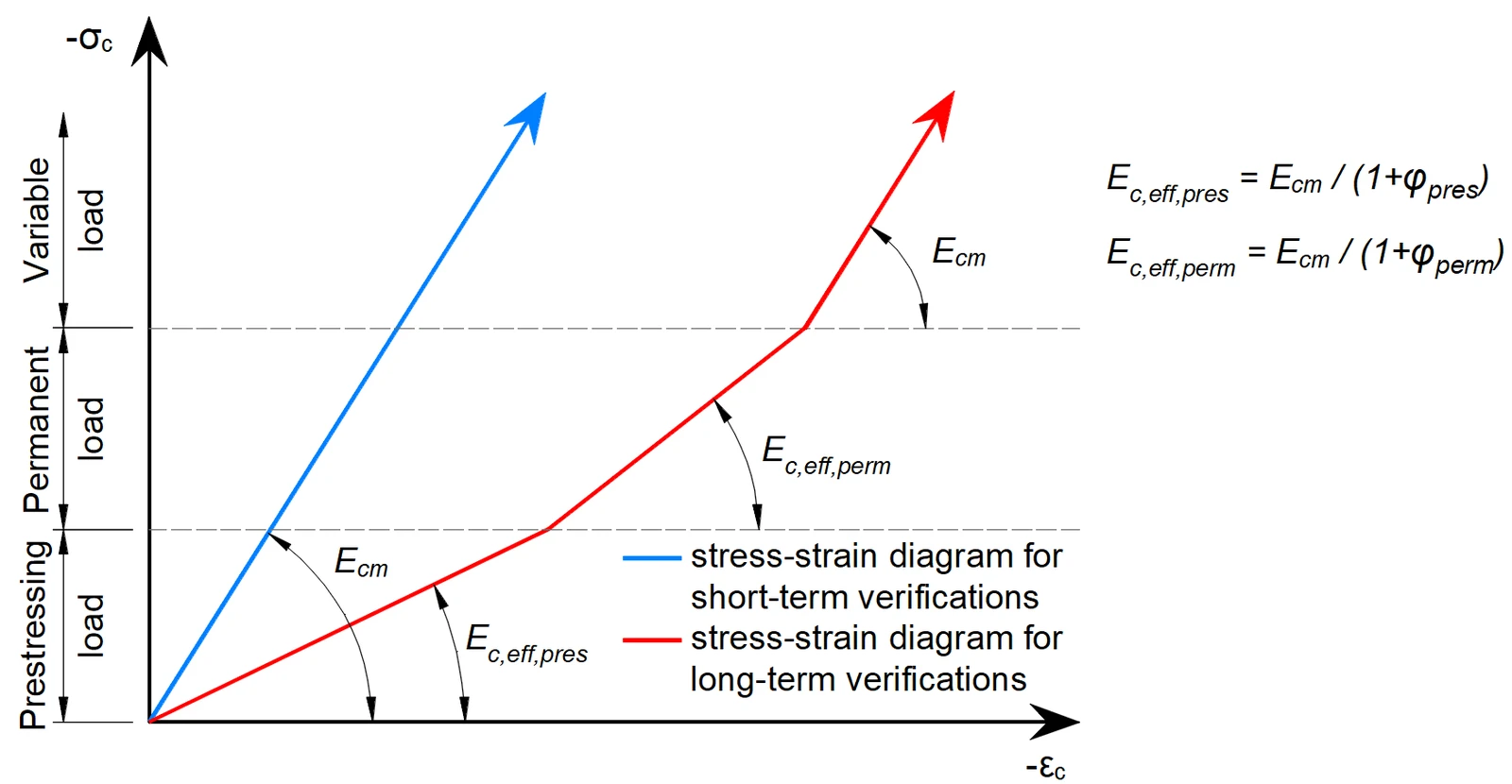
Fig. 26Concrete stress-strain diagrams implemented for serviceability analysis: short- and long-term verifications.\textsf{\textit{\footnotesize{Fig. 26\qquad Concrete stress-strain diagrams implemented for serviceability analysis: short- and long-term verifications.}}}Fig. 26Concrete stress-strain diagrams implemented for serviceability analysis: short- and long-term verifications.

Long term effects

In serviceability analysis, the long-term effects of concrete are considered using an effective infinite creep coefficient (φ\varphiφ, taken as a value of 2.5 by default) which modifies the secant modulus of elasticity of concrete (Ecm) according to EN 1992-1-1, section 3.1.4 (3) resp. 7.4.3 (5) as follows:

Ec,eff=Ecm1+φE_{c,eff} = \frac{E_{cm}}{1+\varphi}Ec,eff​=1+φEcm​​

When considering long-term effects, a load step with all permanent loads is first calculated considering the creep coefficient (i.e., using the effective modulus of elasticity of concrete, Ec,eff) and then the additional loads are calculated without the creep coefficient (i.e., using Ecm). In addition, to conduct short-term verifications, another calculation is performed in which all loads are calculated without the creep coefficient. Both calculations for long and short-term verifications are depicted in Fig. 26.

Creep factors are defined by the user in material properties and shall be calculated according to EN 1992-1-1, Fig 3.1.

Reinforcement

By default, the idealized bilinear stress-strain diagram for the bare reinforcing bars defined in EN 1992-1-1, section 3.2.7 (Fig. 27) is considered. The definition of this diagram only requires the basic properties of the reinforcement to be known during the design phase (strength and ductility class). Whenever known, the actual stress-strain relationship of the reinforcement (hot-rolled, cold-worked, quenched and self-tempered, …) can be considered. The reinforcement stress-strain diagram can be defined by the user, but in this case, it is impossible to assume the tension stiffening effect (it is impossible to calculate crack width). Using the stress-strain diagram with a horizontal top branch does not allow for the verification of structural durability. Therefore, manual verification of standard ductility requirements is necessary.

Fig. 29	Stress-strain diagram of reinforcement: a) bilinear diagram with an inclined top branch; b) bilinear diagram with a horizontal top branch.

Fig. 27 Stress-strain diagram of reinforcement: a) bilinear diagram with an inclined top branch; b) bilinear diagram\textsf{\textit{\footnotesize{Fig. 27 \qquad Stress-strain diagram of reinforcement: a) bilinear diagram with an inclined top branch; b) bilinear diagram}}}Fig. 27 Stress-strain diagram of reinforcement: a) bilinear diagram with an inclined top branch; b) bilinear diagram with a horizontal top branch.\textsf{\textit{\footnotesize{with a horizontal top branch.}}}with a horizontal top branch.

Tension stiffening (Fig. 28)  is accounted for automatically by modifying the input stress-strain relationship of the bare reinforcing bar in order to capture the average stiffness of the bars embedded in the concrete (εm).

Fig. 30	Scheme of tension stiffening.

Fig. 28Scheme of tension stiffening.\textsf{\textit{\footnotesize{Fig. 28\qquad Scheme of tension stiffening.}}}Fig. 28Scheme of tension stiffening.

Related articles

IDEA StatiCa Detail is concrete design software for the structural design and code-check of concrete discontinuity regions. Concrete members stress analysis & concrete wall design.
  • Concrete
  • ACI (USA)
  • EN (Eurocode)
  • Geometry
  • Load effects
  • Overall check
  • Material settings
  • Corbels/Brackets
  • CSFM
  • Cracks
  • Deflections
  • Diaphragms
  • Openings
  • SLS
  • Stress in reinforcement
  • TDA
  • Topology optimization
  • ULS
  • Detail 2D
  • +19
  • Concrete
  • ACI (USA)
  • EN (Eurocode)
  • Geometry
  • Load effects
  • Overall check
  • Material settings
  • Corbels/Brackets
  • CSFM
  • Cracks
  • Deflections
  • Diaphragms
  • Openings
  • SLS
  • Stress in reinforcement
  • TDA
  • Topology optimization
  • ULS
  • Detail 2D

Theoretical background

IDEA StatiCa Detail – Structural design of concrete discontinuities

Read more
Reinforcement template in IDEA StatiCa Detail
  • Concrete
  • ACI (USA)
  • EN (Eurocode)
  • Openings
  • Reinforcement
  • Detail 2D
  • +6
  • Concrete
  • ACI (USA)
  • EN (Eurocode)
  • Openings
  • Reinforcement
  • Detail 2D

Knowledge base

Reinforcement template in IDEA StatiCa Detail

Read more
Code-check of walls and deep beams
  • Concrete
  • Detail 2D
  • EN (Eurocode)
  • BIM link
  • SCIA Engineer
  • CSFM
  • +6
  • Concrete
  • Detail 2D
  • EN (Eurocode)
  • BIM link
  • SCIA Engineer
  • CSFM

Webinar

Code-check of walls and deep beams

Read more