Idea Statica
  • Steel
  • Concrete
  • Support & Learning
  • Pricing
  • Company
  • Steel overview
  • Connection design
  • Member design
  • Parametric design
  • Steel case studies
  • Concrete overview
  • Walls and D-regions
  • Anchoring design
  • Concrete case studies
  • BIM Overview
  • Supported integrations
  • Checkbot
  • Viewer
  • APIs
  • Support Center
  • E-learning & certification
  • Blog
  • Downloads & Licensing
  • Plans
  • Free community tool
  • Enterprise customers
  • Students & educators
  • How much will you save?
  • About us
  • Contact
  • Research & development
  • Authorized resellers
  • Meet our customers
  • Career
  • Steel
    Steel overviewConnection designMember designParametric designSteel case studies
  • Concrete
    Concrete overviewWalls and D-regionsAnchoring designConcrete case studies
  • BIM OverviewSupported integrationsCheckbotViewerAPIs
  • Support & Learning
    Support CenterE-learning & certificationBlogDownloads & Licensing
  • Pricing
    PlansFree community toolEnterprise customersStudents & educatorsHow much will you save?
  • Company
    About usContactResearch & developmentAuthorized resellersMeet our customersCareer
14-Day Trial
14-Day Trial

Subscribe to our newsletter

Company

  • About us
  • Partners
  • Careers
  • Patent

Resources

  • Customer projects
  • Case studies
  • Connection Library
  • Verification books

Legal

  • EULA
  • Privacy policy
  • California Privacy
  • TOS Viewer
  • Licensing

Help

  • Contact
  • Quote request
  • Resellers
  • Downloads
FacebookInstagramLinkedInYouTube

© IDEA StatiCa 2009-2026

Trusted and used worldwide by engineers, fabricators & consultants.

Support CenterVerification examplesConnection to unstiffened flanges
Connection to unstiffened flanges
SteelVerificationsEN (Eurocode)WeldsConnection

Connection to unstiffened flanges

This article is also available in
ENCZDEESFRITPTNLHUROKRPLTHTRVIZH

This article is a selected chapter from book Component-based finite element design of steel connections by prof. Wald et al. The chapter is focused on verification of welds.

Description

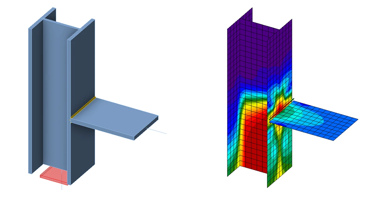
In this chapter, component-based finite element method (CBFEM) of a fillet weld connecting a plate to an unstiffened column is verified on component method (CM). The steel plate is connected to the open and box section columns and loaded in tension.

Analytical model

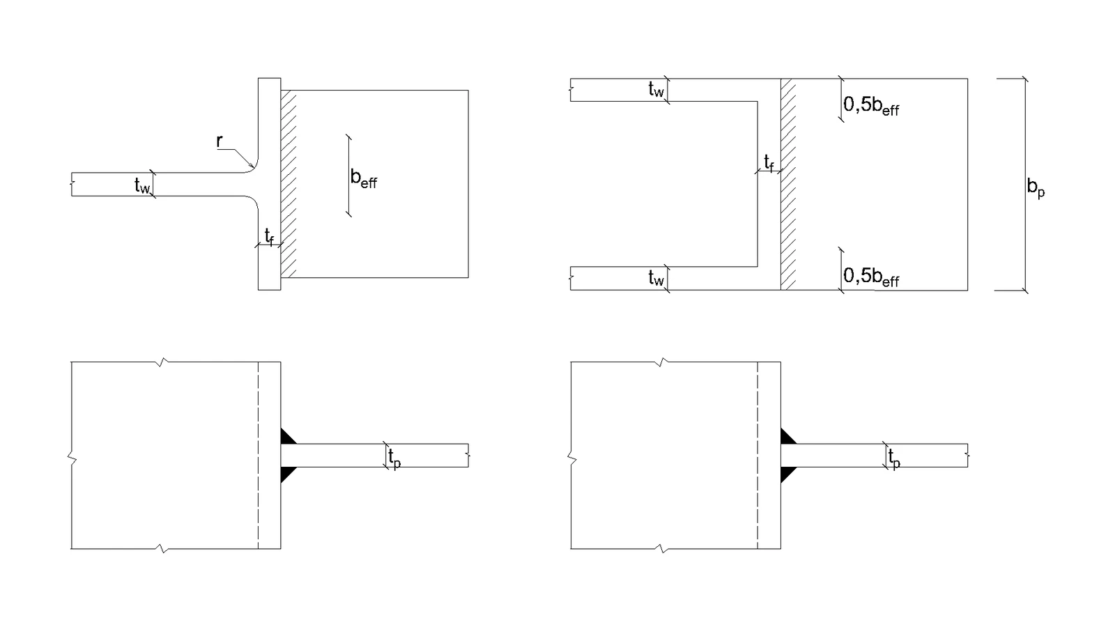
The fillet weld is the only component examined in the study. The welds are designed according to Chapter 4 in EN 1993-1-8:2005 to be the weakest component in the joint. The design resistance of the fillet weld is described in Section 4.1. The force applied perpendicular to a flexible plate, which is welded to an unstiffened section, is limited. The stresses are concentrated in an effective width while the weld resistance around the unstiffened parts is neglected, as shown in Fig. 4.5.1. For an unstiffened I or H section the effective width is obtained according to:

beff=tw+2s+7ktf(4.5.1)b_\mathrm{eff} = t_\mathrm{w} + 2s + 7kt_\mathrm{f} \qquad (4.5.1)beff​=tw​+2s+7ktf​(4.5.1)                                                                    

k=tf⋅fy,ftp⋅fy,p(4.5.2)k = \frac{t_\mathrm{f} \cdot f_\mathrm{y,f} }{ t_\mathrm{p} \cdot f_\mathrm{y,p}} \qquad (4.5.2)k=tp​⋅fy,p​tf​⋅fy,f​​(4.5.2)                                                         

The dimension s is for a rolled section s=rs =rs=r and for a welded section s=2⋅as = \sqrt{2} \cdot as=2​⋅a . For a box or channel section, the effective width should be obtained from:

beff=2tw+5tfbutbeff≤2tw+5ktf(4.5.1)b_\mathrm{eff} = 2t_\mathrm{w} + 5 t_\mathrm{f} \quad \textrm{but}\quad b_\mathrm{eff} \leq 2t_\mathrm{w} + 5 kt_\mathrm{f}\qquad (4.5.1)beff​=2tw​+5tf​butbeff​≤2tw​+5ktf​(4.5.1) 

 σ⊥2 +3⋅(τ⊥2 +τ∥2)≤fuβw⋅γM2\sqrt{  \sigma_{\perp}^2  + 3 \cdot \left( \tau_{\perp}^2  + \tau_{\parallel}^2\right)} \leq \frac{f_u}{\beta_{\mathrm{w}} \cdot \gamma_{\mathrm{M2}}} σ⊥2​ +3⋅(τ⊥2​ +τ∥2​)​≤βw​⋅γM2​fu​​

σ⊥=τ⊥=σN2=Nbeff⋅a⋅12\sigma_{\perp} = \tau_{\perp} = \frac{\sigma_{N}}{\sqrt{2}} = \frac{N}{b_\mathrm{eff} \cdot a}\cdot \frac{1}{\sqrt{2}}σ⊥​=τ⊥​=2​σN​​=beff​⋅aN​⋅2​1​

τ∥=0\tau_{\parallel} = 0τ∥​=0

(σN2)2+3⋅(σN2)2≤fuβw⋅γM2\sqrt{ \left( \frac{\sigma_{N}}{\sqrt{2}} \right)^2 + 3 \cdot \left( \frac{\sigma_{N}}{\sqrt{2}} \right)^2} \leq \frac{f_u}{\beta_{\mathrm{w}} \cdot \gamma_{\mathrm{M2}}}(2​σN​​)2+3⋅(2​σN​​)2​≤βw​⋅γM2​fu​​

(Nbeff⋅a⋅12)2+3⋅(Nbeff⋅a⋅12)2≤fuβw⋅γM2\sqrt{ \left( \frac{N}{b_\mathrm{eff} \cdot a}\cdot \frac{1}{\sqrt{2}} \right)^2 + 3 \cdot \left( \frac{N}{b_\mathrm{eff}\cdot a}\cdot \frac{1}{\sqrt{2}} \right)^2} \leq \frac{f_u}{\beta_{\mathrm{w}} \cdot \gamma_{\mathrm{M2}}}(beff​⋅aN​⋅2​1​)2+3⋅(beff​⋅aN​⋅2​1​)2​≤βw​⋅γM2​fu​​

N≤fu ⋅ beff ⋅ aβw ⋅ γM2 ⋅ 2N \leq \frac{f_{u}  \cdot  b_\mathrm{eff}  \cdot  a }{\beta_{\mathrm{w}}  \cdot  \gamma_{\mathrm{M2}}  \cdot  \sqrt{2}}N≤βw​ ⋅ γM2​ ⋅ 2​fu​ ⋅ beff​ ⋅ a​

Where:

aaa - weld throat thickness

NNN - normal force acting on beam

beffb_\mathrm{eff}beff​ - total effective welds length 

βw\beta_{\mathrm{w}}βw​ - correlation factor taken from EN 1993-1-8 Table 4.1

fuf_ufu​ - nominal ultimate tensile strength of the weaker part joined

γM2\gamma_{\mathrm{M2}}γM2​ - partial safety factor for welds

       Fig. 4.5.1 Effective width of an unstiffened joint (Fig. 4.8 in EN 1993-1-8:2005)\textsf{\textit{\footnotesize{Fig. 4.5.1 Effective width of an unstiffened joint (Fig. 4.8 in EN 1993-1-8:2005)}}}Fig. 4.5.1 Effective width of an unstiffened joint (Fig. 4.8 in EN 1993-1-8:2005)

Numerical model

The weld component in CBFEM is described in General theoretical background and EN theoretical background. The plastic branch is reached in a part of the weld, and stress peaks are redistributed along the weld length.

Verification of resistance

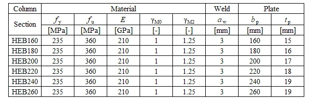
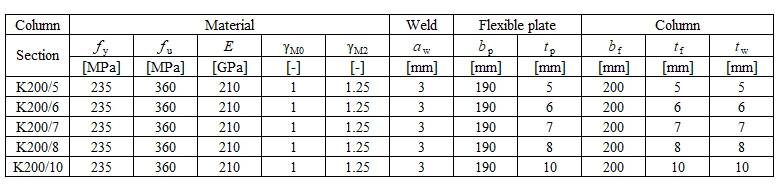
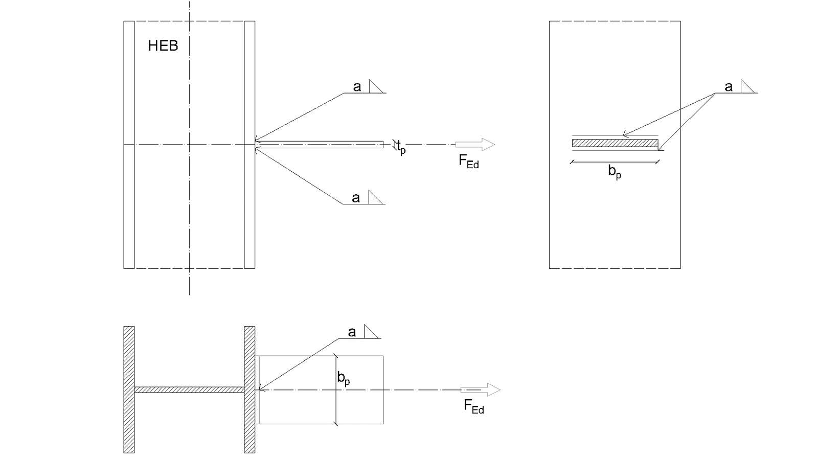
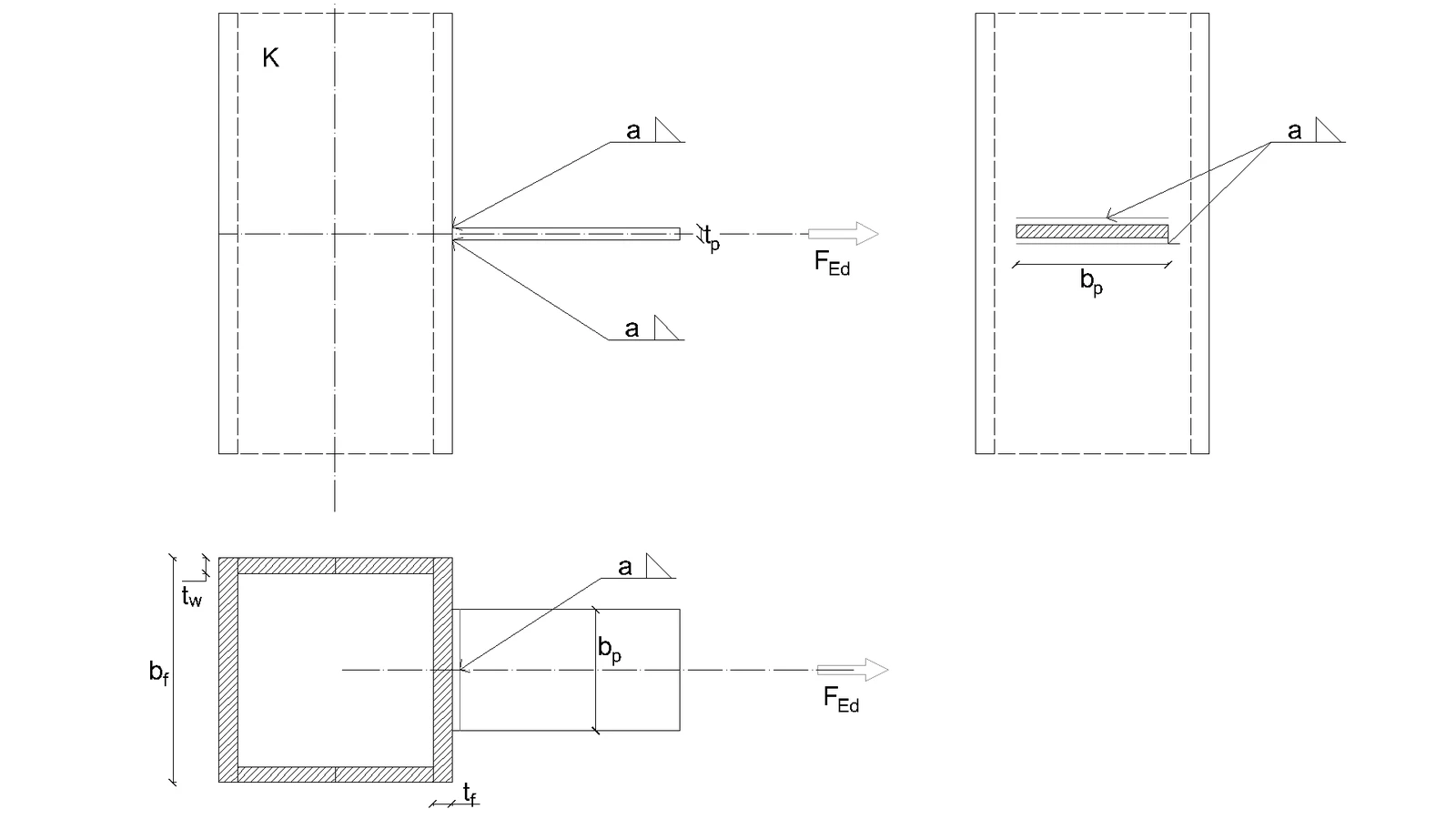
Design resistance calculated by CBFEM is compared with the results of CM. The weld design resistance is compared only. Overview of considered examples and material is given in Tab. 4.5.1. Geometry of joints with dimensions is shown in Fig. 4.5.2.

Tab. 4.5.1 Examples overview\textsf{\textit{\footnotesize{Tab. 4.5.1 Examples overview}}}Tab. 4.5.1 Examples overview

a) Flexible plate to open section             b) Flexible plate to box section\textsf{\textit{\footnotesize{a) Flexible plate to open section             b) Flexible plate to box section}}}a) Flexible plate to open section             b) Flexible plate to box section

Fig. 4.5.2 Joint geometry and dimentions\textsf{\textit{\footnotesize{Fig. 4.5.2 Joint geometry and dimentions}}}Fig. 4.5.2 Joint geometry and dimentions

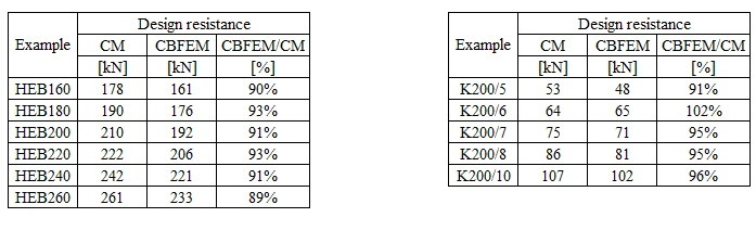
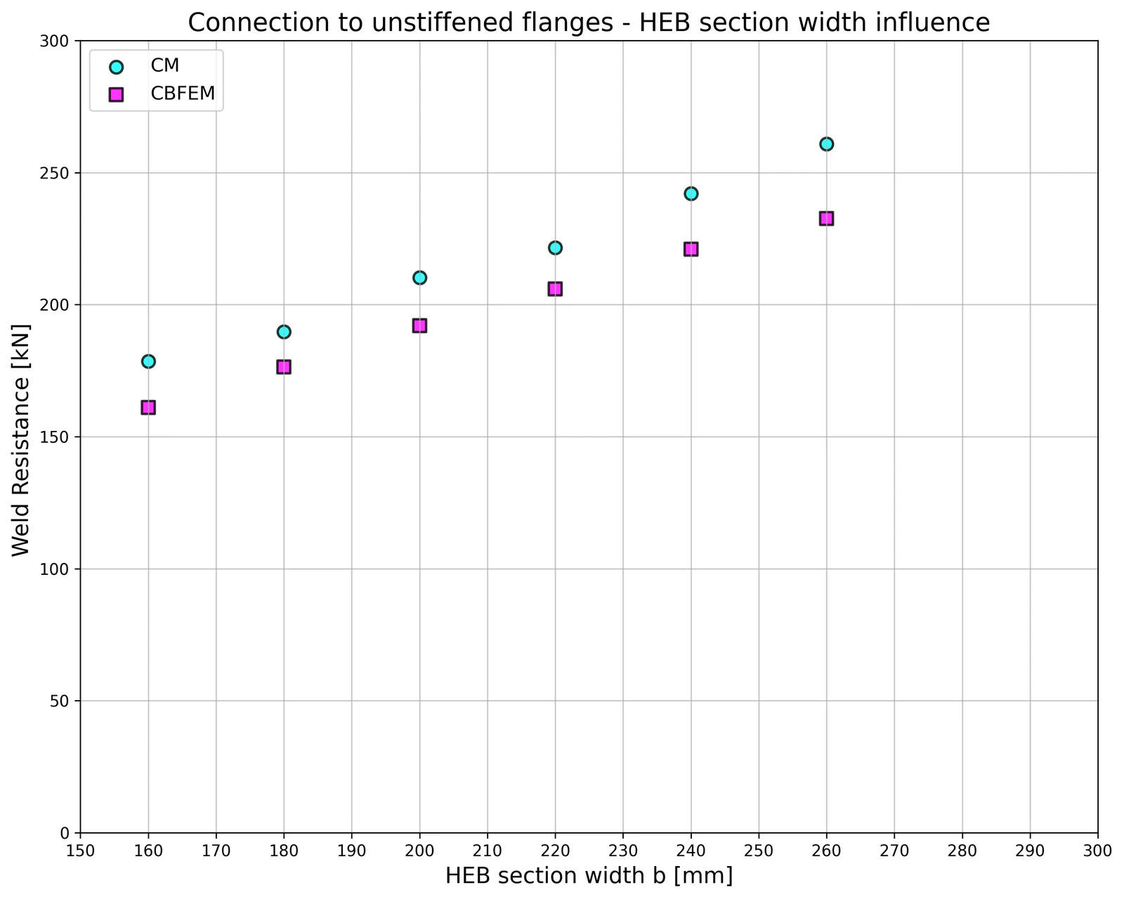
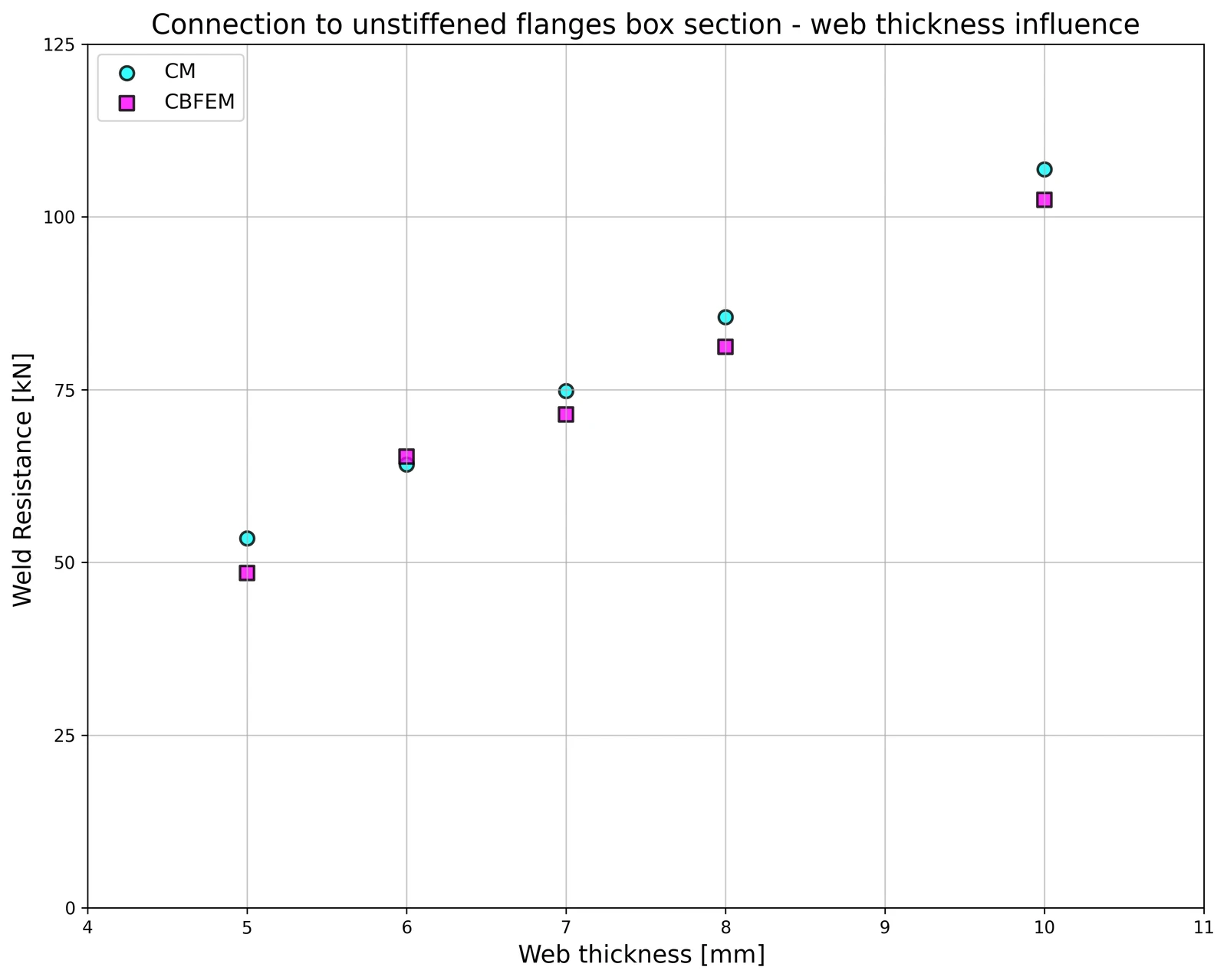
The results are presented in Tab. 4.5.2. The study is performed for two parameters: flange width of the HEB section and web thickness of the box section. The flexible plate is loaded in tension. The influence of the flange width of HEB section on design resistance of a joint is shown in Fig. 4.5.3. The relation between the web thickness of box section on design resistance of a joint is shown in Fig. 4.5.4.

Tab. 4.5.2 Comparison of CBFEM and CM\textsf{\textit{\footnotesize{Tab. 4.5.2 Comparison of CBFEM and CM}}}Tab. 4.5.2 Comparison of CBFEM and CM

Results of CBFEM and CM are compared in a sensitivity study. The influence of the flange width of HEB section on design resistance of a joint is studied in Fig. 4.5.3. The influence of the web thickness of box section on design resistance of a joint is presented in Fig. 4.5.4. The parametric studies show very good agreement of the results for all weld configurations.

Fig. 4.5.3 Flange width of the HEB section      Fig. 4.5.4 Web thickness of the box section\textsf{\textit{\footnotesize{Fig. 4.5.3 Flange width of the HEB section      Fig. 4.5.4 Web thickness of the box section}}}Fig. 4.5.3 Flange width of the HEB section      Fig. 4.5.4 Web thickness of the box section

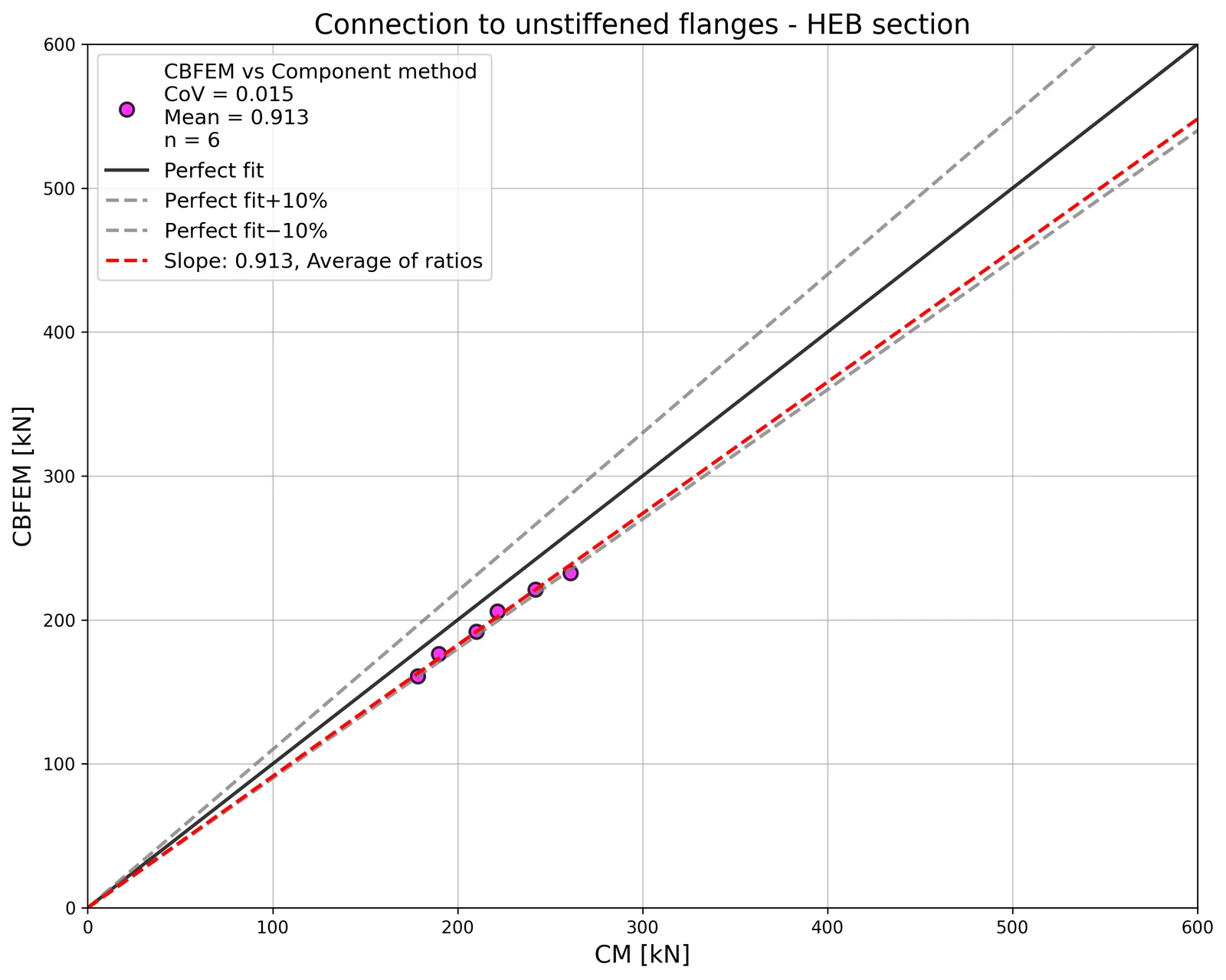
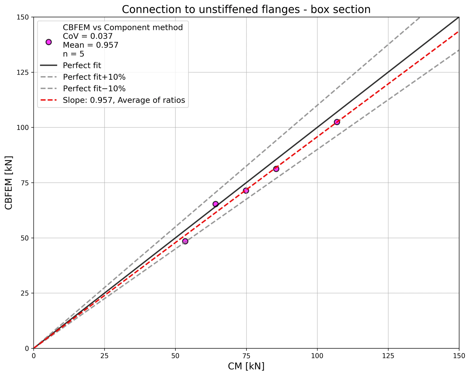
The results of the sensitivity study are summarized in a diagram comparing design resistances of CBFEM and CM; see Fig. 4.5.5 illustrating the accuracy of the CBFEM model.

Fig. 4.5.5 Verification of CBFEM to CM\textsf{\textit{\footnotesize{Fig. 4.5.5 Verification of CBFEM to CM}}}Fig. 4.5.5 Verification of CBFEM to CM

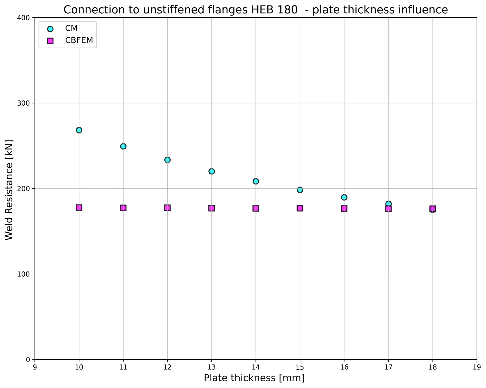
The influence of the plate thickness on the design resistance of the weld is shown in Fig. 4.5.6. The column cross-section is HEB 180 with a flange thickness of 14 mm. A weld connecting a plate thicker than the column flange has the same resistance for CM and CBFEM. On the other hand, the weld connecting the plate to column flange of the same or smaller thickness has in numerical models design resistance smaller by 20%. The plate thickness is not taken into account in numerical models with shell elements, which causes the difference.

Fig. 4.5.6 Influence of plate thickness on the resistance of joint with unstiffened column HEB180\textsf{\textit{\footnotesize{Fig. 4.5.6 Influence of plate thickness on the resistance of joint with unstiffened column HEB180}}}Fig. 4.5.6 Influence of plate thickness on the resistance of joint with unstiffened column HEB180

Benchmark example

Inputs

Column

• Steel S235

• RHS 200/200/5

Flexible plate

• Steel S235

• Thickness tp = 17 mm

• Width bp = 190 mm

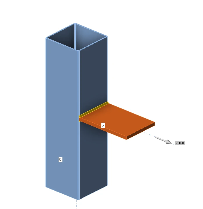
Weld, double fillet welds see Fig. 4.5.7

• Throat thickness aw = 5 mm

Outputs

• Design resistance in tension NRd = 68 kN

Fig. 4.5.7 Benchmark example for the welded connection of plate to unstiffened column\textsf{\textit{\footnotesize{Fig. 4.5.7 Benchmark example for the welded connection of plate to unstiffened column}}}Fig. 4.5.7 Benchmark example for the welded connection of plate to unstiffened column

Open in ViewerDownload