Idea Statica
  • Steel
  • Concrete
  • BIM & Workflows
  • Support & Learning
  • Pricing
  • Company
  • Steel overview
  • Connection design
  • Member design
  • Parametric design
  • Steel case studies
  • Concrete overview
  • Walls and D-regions
  • Anchoring design
  • Concrete case studies
  • BIM Overview
  • Supported integrations
  • Checkbot
  • Viewer
  • APIs
  • Support Center
  • E-learning & certification
  • Blog
  • Downloads & Licensing
  • Plans
  • Free community tool
  • Enterprise customers
  • Students & educators
  • How much will you save?
  • About us
  • Contact
  • Research & development
  • Authorized resellers
  • Meet our customers
  • Career
  • Steel
    Steel overviewConnection designMember designParametric designSteel case studies
  • Concrete
    Concrete overviewWalls and D-regionsAnchoring designConcrete case studies
  • BIM & Workflows
    BIM OverviewSupported integrationsCheckbotViewerAPIs
  • Support & Learning
    Support CenterE-learning & certificationBlogDownloads & Licensing
  • Pricing
    PlansFree community toolEnterprise customersStudents & educatorsHow much will you save?
  • Company
    About usContactResearch & developmentAuthorized resellersMeet our customersCareer
14-Day Trial
14-Day Trial

Subscribe to our newsletter

Company

  • About us
  • Partners
  • Careers
  • Patent

Resources

  • Customer projects
  • Case studies
  • Connection Library
  • Verification books

Legal

  • EULA
  • Global privacy policy
  • California Privacy
  • TOS Viewer
  • Licensing

Help

  • Contact
  • Quote request
  • Resellers
  • Downloads
FacebookInstagramLinkedInYouTube

© IDEA StatiCa 2009-2026

Trusted and used worldwide by engineers, fabricators & consultants.

Support CenterKnowledge Base ArticlesStructural model of a concrete block
Advanced analysis types for your steel structures
Concrete cone area of single anchor and group of anchors
Effective area in check of contact stress in concrete
EN anchoring code-check improvement
Limitations to checks of anchors
Anchorage formulas, tooltips
Calculation of anchors with stand-off
Hooked anchors/L-bolts in AISC
Import of anchoring from Connection to Detail
Automatic anchoring code-selection with hooked anchors
Anchor bolts
Structural model of a concrete block
Code-check of anchors (EN)
Code-check of concrete blocks (EN)
Code-check of anchors (AISC)
Code-check of concrete blocks (AISC)
Code-check of anchors according to Canadian standards
Code-check of concrete block according to Canadian standards
Code-check of anchors according to Australian standards
Check of anchor tension as a bolt tension option (AS)
Code-check of concrete block according to Australian standards
Russian Standard (SP) anchorage
Code-check of anchors according to Chinese standard
Code-check of concrete block according to Chinese standard
Code-check of concrete block according to Hong Kong Code
Code-check of concrete block according to Indian standards
Check of anchors according to STO
Code-check of concrete block according to Russian standards
Check of concrete block according to SP - new
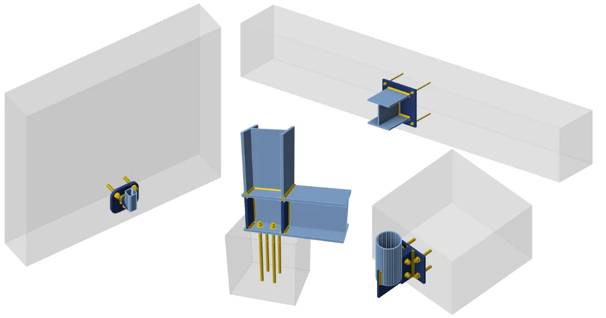
Structural design of steel connections and concrete members. A concrete block is not modeled but only simulated by Winkler subsoil model with uniform stiffness.
SteelConnection designKnowledge baseConnectionAISC (USA)

Structural model of a concrete block

This article is also available in
ENCZDEESFRITPTNLHUROKRPLTHTRVIZH

Design model

In CBFEM, it is convenient to simplify the concrete block as 2D contact elements. The connection between the concrete and the base plate resists in compression only. Compression is transferred via the Winkler-Pasternak subsoil model, representing deformations of the concrete block. The tension force between the base plate and concrete block is carried by the anchor bolts. The shear force is transferred by friction between a base plate and a concrete block, by shear key and by bending of anchor bolts and friction. The resistance of bolts in shear is assessed analytically. Friction and shear key are modeled as a full single point constraint in the plane of the base plate – concrete contact.

Deformation stiffness

The stiffness of the concrete block may be predicted for the design of column bases as an elastic hemisphere. A Winkler-Pasternak subsoil model is commonly used for a simplified calculation of foundations. The stiffness of subsoil is determined using modulus of elasticity of concrete and the effective height of a subsoil as:

k=Ec(α1+υ)AeffAref(1ha2d+a3+a4)k = \frac{E_c}{(\alpha_1 + \upsilon) \sqrt{\frac{A_{eff}}{A_{ref}}}} \left( \frac{1}{\frac{h}{a_2 d} + a_3}+a_4 \right)k=(α1​+υ)Aref​Aeff​​​Ec​​(a2​dh​+a3​1​+a4​)

where:

  • k – stiffness of concrete subsoil in compression
  • Ec – modulus of elasticity of concrete
  • υ – Poisson's coefficient of the concrete block
  • Aeff – effective area in compression
  • Aref = 1 m2 – reference area
  • d – base plate width
  • h – concrete block height
  • a1 = 1.65; a2 = 0.5; a3 = 0.3; a4 = 1.0 – coefficients

SI units must be used in the formula, the resulting unit is N/m3.

Transfer of shear load at the base plate

The shear load at the base plate can be transferred by three means:

  • Friction
  • Shear lug
  • Anchors

Users can choose the mean by editing the base plate operation. No combination of means is allowed in the software, however, EN 1993-1-8 – Cl. 6.2.2 and Fib 58 – Chapter 4.2 allows for the combination of shear transfer by anchors and friction under certain conditions. In general, it is conservative to neglect friction in the anchorage design, although it may in some cases lead to an underestimation of concrete cracking at the serviceability level. As a rule, frictional resistance should be neglected if:

  • the thickness of the grout layer exceeds one-half the anchor diameter,
  • the anchorage capacity is governed by a near-edge condition,
  • the anchorage is intended to resist earthquake loads.

The combination with a shear lug should never be allowed due to the deformation compatibility.

Transfer of shear load by friction

The shear resistance equals the resistance safety factor multiplied by friction coefficient editable in Code setup and compressive load. The compressive load includes all forces, e.g. in case of a column base loaded by compressive force and bending moment, the compressive load used for frictional shear resistance might be higher than the applied compressive force.

Transfer of shear load by shear lug

The shear lug is simulated as a stub encased in concrete under the base plate. The shear load is estimated to be transferred by uniform load distribution acting on the whole portion of the shear lug embedded in the concrete block, i.e. all nodes of the shear lug below the concrete surface are uniformly loaded. The portion of the shear lug above the concrete surface in grout is not assumed to transfer the shear load.

Be aware that the lever arm between the applied shear load (at the base plate) and the shear resistance (half-height of the shear lug embedded in concrete) causes a bending moment which must be transferred by compressive force in concrete and tensile forces in anchors.

The shear lug consists of shell finite elements and is checked as regular plates. Also, the welds of the shear lug to the base plate are checked using standard procedures in IDEA StatiCa Connection. Manual calculation usually assumes beam theory for the shear lug, although it is not accurate because the length to width ratio is very small for shear lug. Therefore, there might be a significant difference between IDEA StatiCa Connection and manual calculation.

Transfer of shear load by anchors

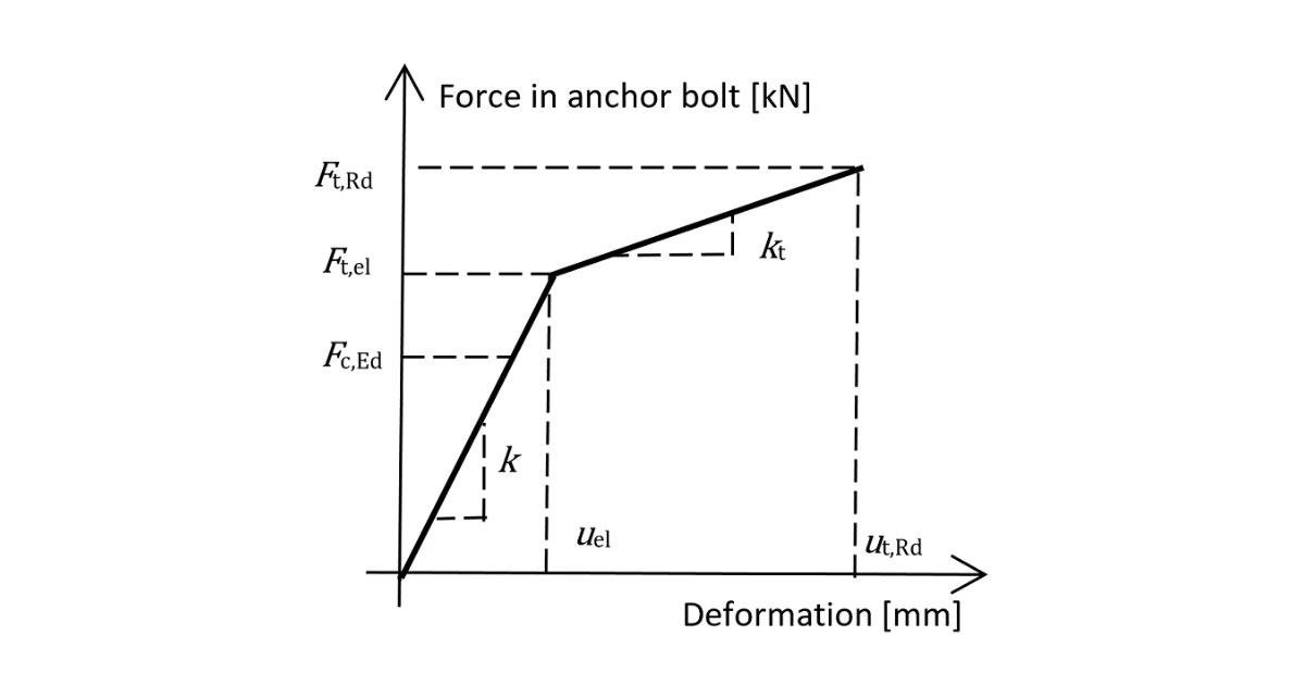
The shear resistance is determined by the shear resistance of anchors. The steel resistance of anchors have elastoplastic load-deformation curve, but the concrete failure modes are considered as perfectly brittle.
Related articles

IDEA StatiCa Connection – Structural design of steel connections
  • Steel
  • Connection
  • EN (Eurocode)
  • AISC (USA)
  • AS (Australia)
  • CSA (Canada)
  • IS (India)
  • GB (China)
  • HKG (Hong Kong)
  • SP 16 (Russia)
  • CBFEM
  • +11
  • Steel
  • Connection
  • EN (Eurocode)
  • AISC (USA)
  • AS (Australia)
  • CSA (Canada)
  • IS (India)
  • GB (China)
  • HKG (Hong Kong)
  • SP 16 (Russia)
  • CBFEM

Theoretical background

IDEA StatiCa Connection – Structural design of steel connections

Read more
IDEA StatiCa Connection theoretical background for the advanced structural design of steel connections. Description of anchor bolts and their stiffness including anchors with stand-off. Structural design of welded and bolted connections.
  • Steel
  • Connection
  • AISC (USA)
  • AS (Australia)
  • CSA (Canada)
  • EN (Eurocode)
  • IS (India)
  • GB (China)
  • HKG (Hong Kong)
  • Anchoring
  • CBFEM
  • Steel-to-concrete
  • SP 16 (Russia)
  • +13
  • Steel
  • Connection
  • AISC (USA)
  • AS (Australia)
  • CSA (Canada)
  • EN (Eurocode)
  • IS (India)
  • GB (China)
  • HKG (Hong Kong)
  • Anchoring
  • CBFEM
  • Steel-to-concrete
  • SP 16 (Russia)

Knowledge base

Anchor bolts

Read more
Connection Wednesdays – Focus on anchoring
  • Steel
  • Connection
  • Anchoring
  • +3
  • Steel
  • Connection
  • Anchoring

Webinar

Connection Wednesdays – Focus on anchoring

Read more
General anchoring shapes and options
  • Steel
  • Connection
  • Geometry
  • Anchoring
  • Concrete block
  • Plates
  • Steel-to-concrete
  • Hilti
  • +8
  • Steel
  • Connection
  • Geometry
  • Anchoring
  • Concrete block
  • Plates
  • Steel-to-concrete
  • Hilti

Knowledge base

General anchoring shapes and options

Read more