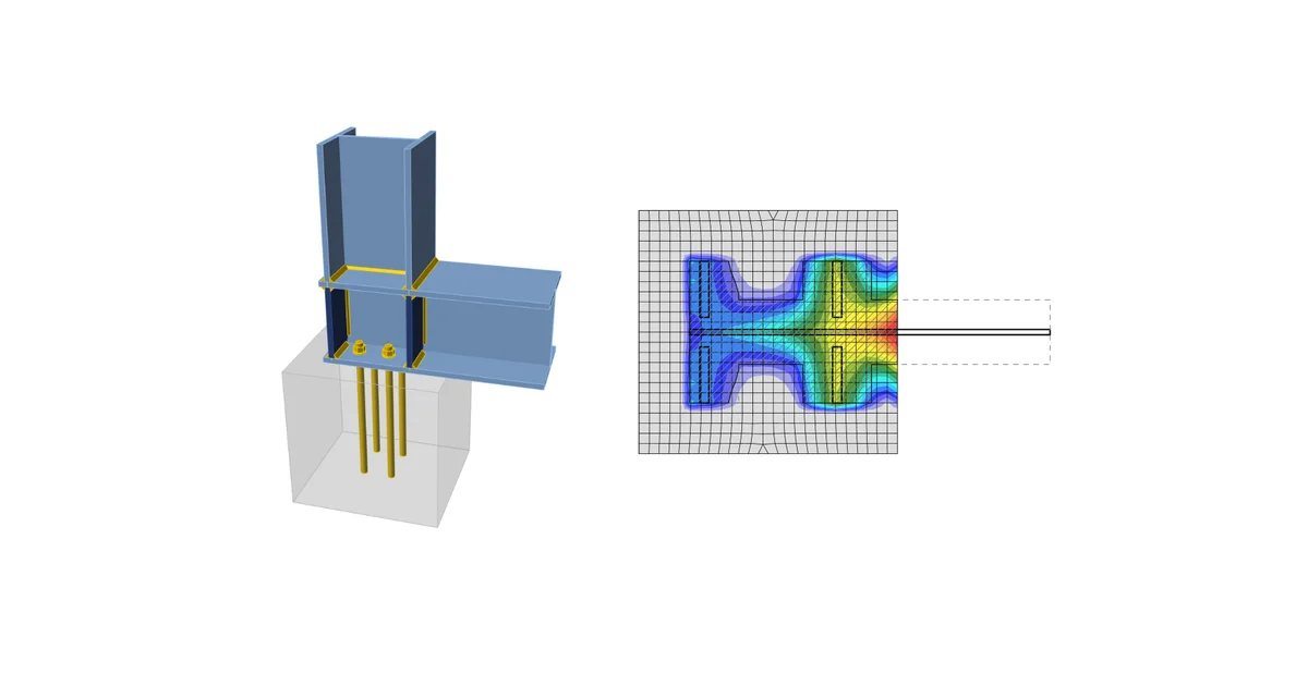
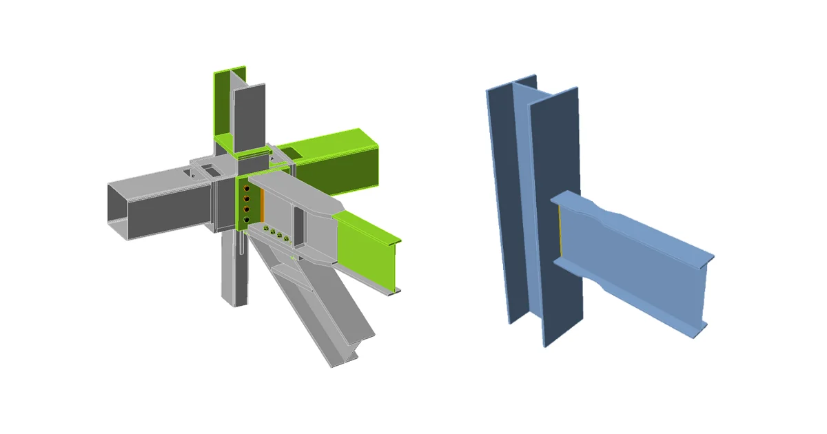
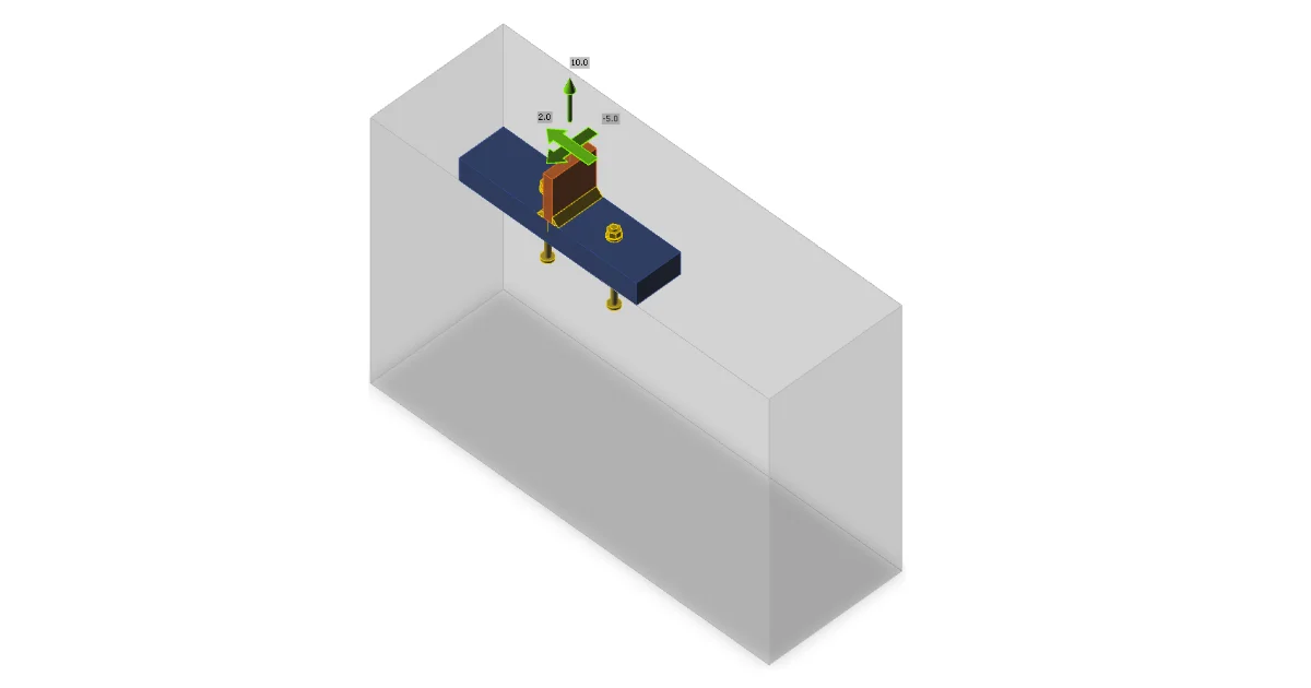
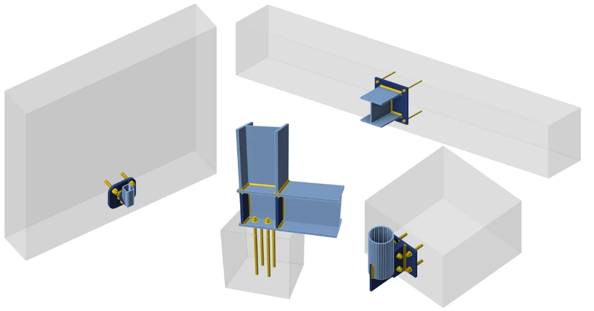
The forces in anchors including prying forces are determined by finite element analysis, but the resistances are checked using code provisions of A23.3 - Annex D.
Anchor rods are designed according to A23.3-14 – Annex D. The following resistances of anchor bolts are evaluated:
- Steel strength of anchor in tension Nsar,
- Concrete breakout strength in tension Ncbr,
- Concrete pullout strength Npr,
- Concrete side-face blowout strength Nsbr,
- Steel strength of anchor in shear Vsar,
- Concrete breakout strength in shear Vcbr,
- Concrete pryout strength of anchor in shear Vcpr.
The concrete condition may be chosen by user as cracked or non-cracked. The type of anchors (cast-in headed with circular or rectangular washers, straight anchors) is selected by user, the pullout strength and side-face blowout strength are checked in the software only for headed anchors.
Following checks of anchors loaded in tension are not provided and should be checked using information in relevant Technical Product Specification (based on the 5 percent fractile of tests):
- Pull-out failure of fastener (for post-installed mechanical anchors) – CSA A23.3-14: D.6.3,
- Bond strength of adhesive anchor (for post-installed bonded anchors) – CSA A23.3-14: D.6.5.
Anchors shall satisfy the required edge distances, spacings, and thicknesses to preclude splitting failure as required by CSA A23.3-14: D.9.
Steel resistance of anchor in tension
Steel strength of anchor in tension is determined according to CSA A23.3-14 – D.6.1 as
Nsar = Ase,N ϕs futa R
where:
- ϕs = 0.85 – steel embedment material resistance factor for reinforcement
- Ase,N – effective cross-sectional area of an anchor in tension
- futa ≤ min (860 MPa, 1.9 fya) – specified tensile strength of anchor steel
- fya – specified yield strength of anchor steel
- R = 0.8 – resistance modification factor as specified in CSA A23.3.-14 – D.5.3
Concrete breakout resistance of anchor in tension
Concrete breakout strength is designed according to the Concrete Capacity Design (CCD) in CSA A23.3-14 – D.6.2. In the CCD method, the concrete cone is considered to be formed at an angle of approximately 34° (1 vertical to 1.5 horizontal slope). For simplification, the cone is considered to be square rather than round in plan. The concrete breakout stress in the CCD method is considered to decrease with an increase in the size of the breakout surface.
where:
- ANc – concrete breakout cone area for a group of anchors loaded by the tension that creates a common concrete cone
- ANco = 9 hef2 – concrete breakout cone area for single anchor not influenced by concrete edges
- – modification factor for edge distance
- ca,min – the smallest distance from the anchor to the edge
- hef – depth of embedment; according to A23.3-14 – D.6.2.3, the effective embedment depth hef is reduced to if anchors are located less than 1.5 hef from three or more edges
- – modification factor for eccentrically loaded group of anchors
- e'N – tension load eccentricity with respect to the center of gravity of anchors loaded by tension and creating a common concrete cone
- Ψc,N – modification factor for concrete conditions; Ψc,N = 1 for cracked concrete, Ψc,N = 1.25 for non-cracked concrete
- – basic concrete breakout strength of a single anchor in tension in cracked concrete; for cast-in headed anchors and 275 mm ≤ hef ≤ 625 mm,
- ϕc=0.65 – resistance factor for concrete
- kc=10 for cast-in anchors
- s – spacing between anchors
- ca,max – maximum distance from an anchor to one of the three close edges
- λa = 1 – is modification factor for lightweight concrete
- f'c – concrete compressive strength [MPa]
- R = 1 – resistance modification factor as specified in CSA A23.3 – D.5.3
According to A23.3-14 – D.6.2.8, in case of headed anchors, the projected surface area ANc is determined from the effective perimeter of the washer plate, which is the lesser value of da + 2 twp or dwp, where:
- da – anchor diameter
- dwp – washer plate diameter or edge size
- twp – washer plate thickness
The group of anchors is checked against the sum of tensile forces in anchors loaded in tension and creating a common concrete cone.
The concrete breakout cone area for group of anchors loaded by tension that create common concrete cone, Ac,N, is shown by red dashed line.
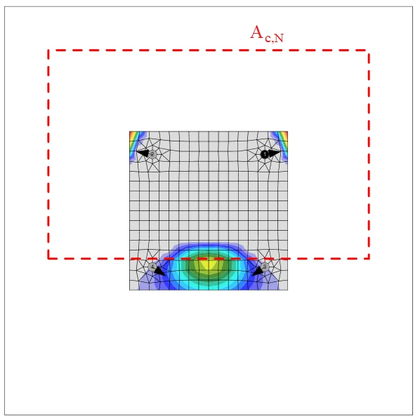
According to CSA A23.3-14 – D.6.2.9, where anchor reinforcement is developed in accordance with Clause 12 of A23.3-14 on both sides of the breakout surface, the anchor reinforcement is presumed to transfer the tension forces, and concrete breakout strength is not evaluated (can be set in Code setup).
Concrete pullout resistance of anchor in tension
Concrete pullout strength of a headed anchor is defined in CSA A23.3-14 – D.6.3 as
Ncpr = Ψc,P Npr
where:
- Ψc,P – modification factor for concrete condition; Ψc,P = 1.0 for cracked concrete, Ψc,P = 1.4 for non-cracked concrete
- Npr = 8 Abrg ϕc f'c R for headed anchor
- Abrg – bearing area of the head of stud or anchor bolt
- ϕc = 0.65 – resistance factor for concrete
- da – anchor diameter
- f'c – concrete compressive strength
- R = 1 – resistance modification factor as specified in CSA A23.3 – D.5.3
Concrete pullout strength for other types of anchors than headed is not evaluated in the software and has to be specified by the manufacturer.
Concrete side-face blowout resistance
Concrete side-face blowout strength of headed anchor in tension is defined in CSA A23.3-14 – D.6.4 as:
If ca2 for the single anchor loaded in tension is less than 3 ca1, the value of Nsbr is multiplied by the factor 0.5 ≤ (1+ ca2 / ca1) / 4 ≤ 1.
D.6.4.2 requires that a group of headed anchors with deep embedment close to an edge (hef > 2.5 ca1) and spacing between anchors less than 6 ca1 has the strength:
Only one reduction factor at a time is applied.
IDEA StatiCa always checks each anchor independently for side-face blowout strength and thus no anchor group of two anchors is assumed and rather the reduction factor is divided by two. This provides the same result if the tensile forces in each anchor are the same and a safe-sided assumption if the forces differ. The reduction factor used in IDEA StatiCa is:
where:
- ca1 – the shorter distance from an anchor to an edge
- ca2 – the longer distance, perpendicular to ca1, from an anchor to an edge
- Abrg – a bearing area of the head of stud or anchor bolt
- ϕc – resistance factor for concrete editable in Code setup
- f'c – concrete compressive strength
- hef – depth of embedment; according to A23.3-14 – D.6.2.3, the effective embedment depth hef is reduced to if anchors are located less than 1.5 hef from three or more edges
- s – spacing between anchors
- R = 1 – resistance modification factor as specified in CSA A23.3 – D.5.3
Steel resistance of anchor in shear
The steel strength in shear is determined according to A23.3 – D.7.1 as
Vsar = Ase,V ϕs 0.6 futa R
where:
- ϕs = 0.85 – steel embedment material resistance factor for reinforcement
- Ase,V – effective cross-sectional area of an anchor in shear
- futa – specified tensile strength of anchor steel but not greater than the smaller of 1.9 fya or 860 MPa
- R = 0.75 – resistance modification factor as specified in CSA A23.3 – D.5.3
If mortar joint is selected, steel strength in shear Vsa is multiplied by 0.8 (A23.3 –D.7.1.3).
The shear on lever arm, which is present in case of base plate with oversized holes and washers or plates added to the top of the base plate to transmit the shear force, is not considered.
Concrete breakout resistance of anchor in shear
Concrete breakout strength of an anchor in shear is designed according to A23.3 –D.7.2. The shear force acting on a base plate is assumed to be transferred by the anchors which are closest to the edge in the direction of the shear force. The direction of the shear force with respect to the concrete edge affects the concrete breakout strength according to FIB Bulletin 58 – Design of anchorages in concrete – Guide to good practice (2011). If concrete cones of anchors overlap, they create a common concrete cone. The eccentricity in shear is also taken into account.
where:
- AVc – projected concrete failure area of an anchor or group of anchors divided by number of anchors in this group
- AVco = 4.5 ca12 – projected concrete failure area of one anchor when not limited by corner influences, spacing or member thickness
- – modification factor for group of anchors loaded eccentrically in shear
- – modification factor for edge effect
- Ψc,V – modification factor for concrete condition; Ψc,V = 1.0 for cracked concrete, Ψc,V = 1.4 for non-cracked concrete
- – modification factor for anchors located in a concrete member where ha < 1.5 ca1
- – modification factor for anchors loaded at an angle with the concrete edge (FIB Bulletin 58 – Design of anchorages in concrete – Guide to good practice, 2011)
- ha – height of a failure surface on the concrete side
- le = hef ≤ 8 da – load-bearing length of the anchor in shear
- da – anchor diameter
- f'c – concrete compressive strength
- ca1 – edge distance in the direction of load; according to Cl. 17.5.2.4, for a narrow member, c2,max < 1.5 c1 that is also deemed to be thin, ha < 1.5 c1, c'1 is used in previous equations instead of c1; the reduced c'1 = max (c2,max / 1.5, ha / 1.5, sc,max / 3)
- ca2 – edge distance in the direction perpendicular to load
- c2,max – largest edge distance in the direction perpendicular to load
- sc,max – maximum spacing perpendicular to direction of shear, between anchors within a group
- ϕc = 0.65 – resistance factor for concrete
- R = 1 – resistance modification factor as specified in CSA A23.3 – D.5.3
If both edge distances ca2 ≤ 1.5ca1 and ha ≤ 1.5 ca1, , where s is the maximum spacing perpendicular to direction of shear, between anchors within a group.
According to A23.3-14 – D.7.2.9, where anchor reinforcement is developed in accordance with A23.3-14 – Clause 12 on both sides of the breakout surface, the anchor reinforcement is presumed to transfer the shear forces and concrete breakout strength is not evaluated.
Concrete pryout resistance of an anchor in shear
Concrete pryout strength is designed according to A23.3 – D.7.3.
Vcpr = kcp Ncpr
where:
- kcp = 1.0 for hef < 65 mm, kcp = 2.0 for hef ≥ 65 mm
- Ncpr – concrete breakout strength – all anchors are considered to be in tension
According to CSA A23.3-14 – D.6.2.9, where anchor reinforcement is developed in accordance with Clause 12 of A23.3-14 on both sides of the breakout surface, the anchor reinforcement is presumed to transfer the tension forces and concrete breakout strength is not evaluated (can be set in Code setup).
Interaction of tensile and shear forces
Interaction of tensile and shear forces is assessed according to A23.3 – Figure D.18.
where:
- Nf and Vf – design forces acting on an anchor
- Nr and Vr – the lowest design strengths determined from all appropriate failure modes
Anchors with stand-off
Anchor with stand-off is designed as a bar element loaded by shear force, bending moment and compressive or tensile force. These internal forces are determined by the finite element model. The anchor is fixed on both sides, one side is 0.5×d below the concrete level, the other side is in the middle of the thickness of the plate. The buckling length is conservatively assumed as twice the length of the bar element. Plastic section modulus is used. The bar element is designed according to S16-14. Interaction of shear force is neglected because the minimum length of the anchor to fit the nut under the base plate ensures that the anchor fails in bending before the shear force reaches half the shear resistance, and the shear interaction is negligible (up to 7 %). Interaction of bending moment and compressive or tensile force is conservatively assumed as linear. Second-order effects are not taken into account.
Shear resistance (CSA S16-14 – 13.4.4):
Vr = ϕ ∙ 0.66 ∙ Av ∙ Fy
- Av = 0.844 ∙ As – the shear area
- As – the bolt area reduced by threads
- Fy – bolt yield strength
- ϕ – the resistance factor, the recommended value is 0.9
Tensile resistance (CSA S16-14 – 13.2)
Tr = ϕ ∙ As ∙ Fy
Compressive resistance (CSA S16-14 – 13.3.1)
- – anchor bolt slenderness
- – elastic buckling stress
- KL = 2 ∙ l – buckling length
- l – length of the bolt element equal to half the base plate thickness + gap + half the bolt diameter
- – radius of gyration of the anchor bolt
- – moment of inertia of the bolt
- n = 1.34 – parameter for compressive resistance
Bending resistance (CSA S16-14 – 13.5):
Mr = ϕ ∙ Z ∙ Fy
Z = ds3 / 6 – plastic section modulus of the bolt
Linear interaction:
... for compressive normal force
... for tensile normal force
- N – tensile (positive) or compressive (negative sign) factored force
- Cr – factored compressive (negative sign) resistance
- Tr – factored tensile (positive sign) resistance
- M – factored bending moment
- Mr – factored moment resistance
Detailing
The spacing between anchors should be greater than four times the anchor diameter according to A23.3-14 – D.9.2.
Edge distances to steel plate follow the rules of bolts, i.e. according to S16-14 – 22.3. minimum edge distance (1.25 d – editable in Code setup) is checked.