Idea Statica
  • Steel
  • Concrete
  • Support & Learning
  • Pricing
  • Company
  • Steel overview
  • Connection design
  • Member design
  • Parametric design
  • Steel case studies
  • Concrete overview
  • Walls and D-regions
  • Anchoring design
  • Concrete case studies
  • BIM Overview
  • Supported integrations
  • Checkbot
  • Viewer
  • APIs
  • Support Center
  • E-learning & certification
  • Blog
  • Downloads & Licensing
  • Plans
  • Free community tool
  • Enterprise customers
  • Students & educators
  • How much will you save?
  • About us
  • Contact
  • Research & development
  • Authorized resellers
  • Meet our customers
  • Career
  • Steel
    Steel overviewConnection designMember designParametric designSteel case studies
  • Concrete
    Concrete overviewWalls and D-regionsAnchoring designConcrete case studies
  • BIM OverviewSupported integrationsCheckbotViewerAPIs
  • Support & Learning
    Support CenterE-learning & certificationBlogDownloads & Licensing
  • Pricing
    PlansFree community toolEnterprise customersStudents & educatorsHow much will you save?
  • Company
    About usContactResearch & developmentAuthorized resellersMeet our customersCareer
14-Day Trial
14-Day Trial

Subscribe to our newsletter

Company

  • About us
  • Partners
  • Careers
  • Patent

Resources

  • Customer projects
  • Case studies
  • Connection Library
  • Verification books

Legal

  • EULA
  • Privacy policy
  • California Privacy
  • TOS Viewer
  • Licensing

Help

  • Contact
  • Quote request
  • Resellers
  • Downloads
FacebookInstagramLinkedInYouTube

© IDEA StatiCa 2009-2026

Trusted and used worldwide by engineers, fabricators & consultants.

Support CenterKnowledge Base ArticlesSlotted holes for the selected plate
How to set position of bolts
How to define preloaded bolts
Bolts and preloaded bolts connections
Prying and high tension force in bolts
Autodesign of bolts
Steel pins
Slotted holes for the selected plate
Distance between plates connected by a contact
Limitations of through bolts and hollow sections
Through bolts for hollow sections warning
Advanced anchoring design and anchors in Connection
Slotted holes for the selected plate
Connection designSteelMember designKnowledge basev25.0

Slotted holes for the selected plate

This article is also available in
ENCZDEESFRITPTNLHUROKRPLTHTRVIZH

Slotted or oval holes for bolts can be assigned to any plate of the bolted connection, even to multiple plates. This enables designers to decide about the structural behavior and constructability of the joint.

Users can model real-world conditions more accurately by selecting which plate will include slotted holes, e.g., either in the fin plate or in the web of the connected member, as is typical in floor beam connections. 

If the design requires it, slotted holes can also be applied to multiple plates. Previously, users couldn’t define the location of slotted holes, leading to incorrect bolt checks. With this improvement, bolt checks are now aligned with the actual design scenario.

Where can the slotted holes be used?

  • The slotted holes can be set to any plate that is contained in the bolt assembly
  • They can be set to one or more plates
  • They can be defined for plates of the analyzed member

Defining slotted holes

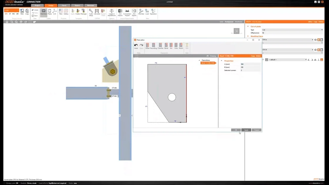
The shape of the bolt holes can be changed in the Editor of the plate. You can open the Editor by selecting the plate in the 3D scene with the right mouse button. Another option is to use the Editor button in the operation header (the orange strip).
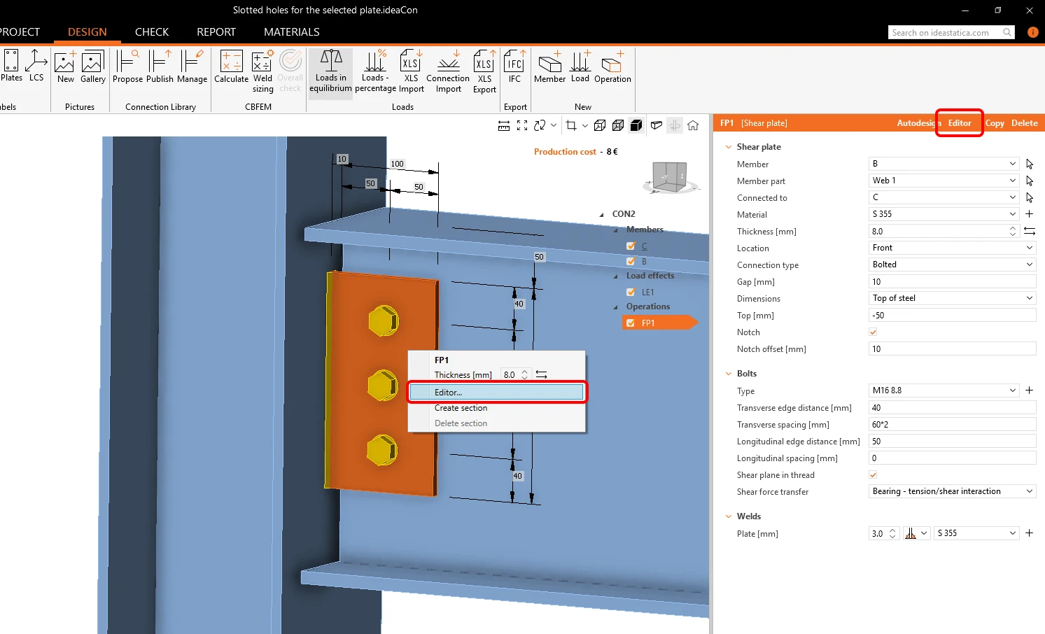
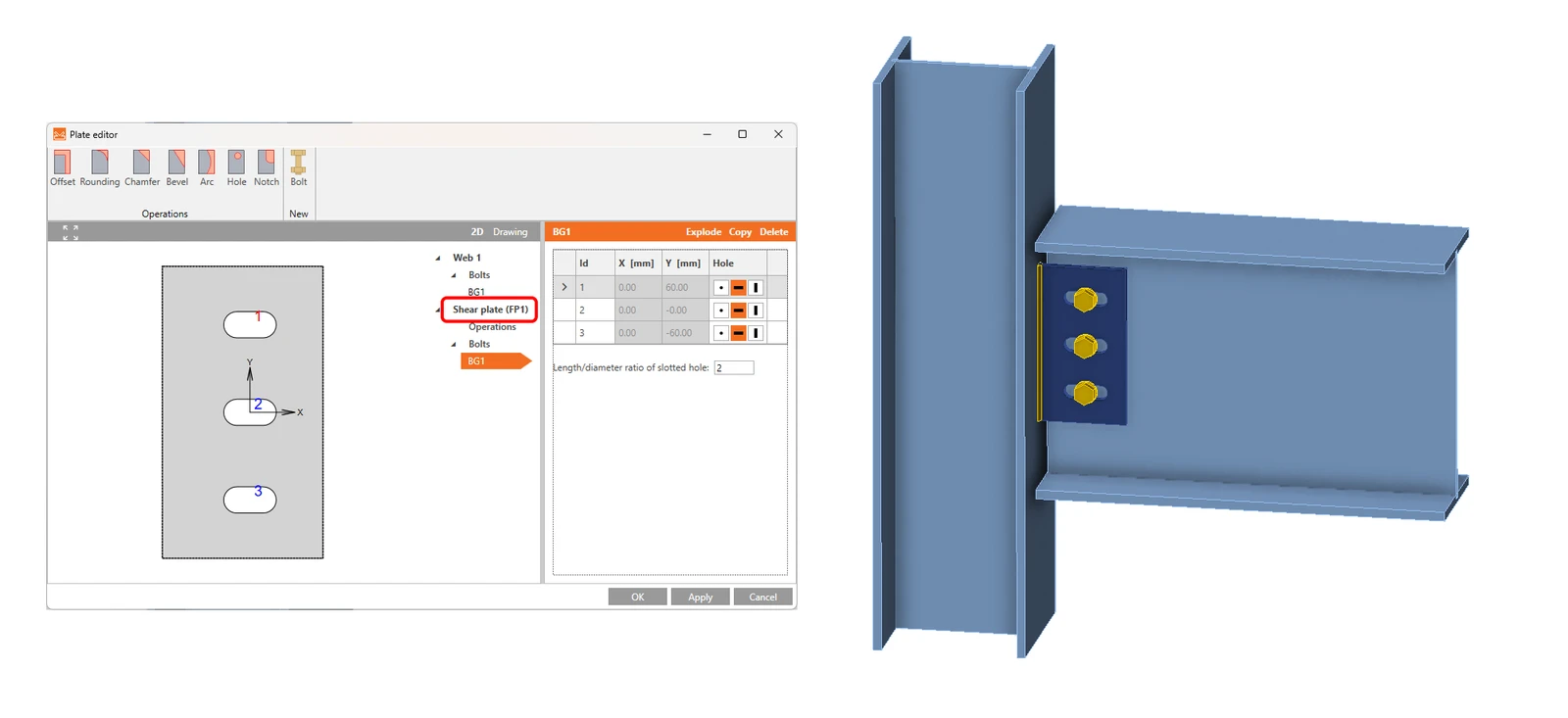
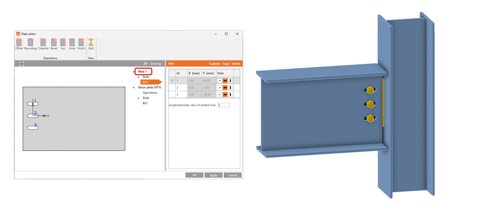
In the plate Editor of the plate containing the bolt, there is a list of all the plates that are connected by selected bolts. In the list, you can define, on which plate the holes will be changed to slotted.

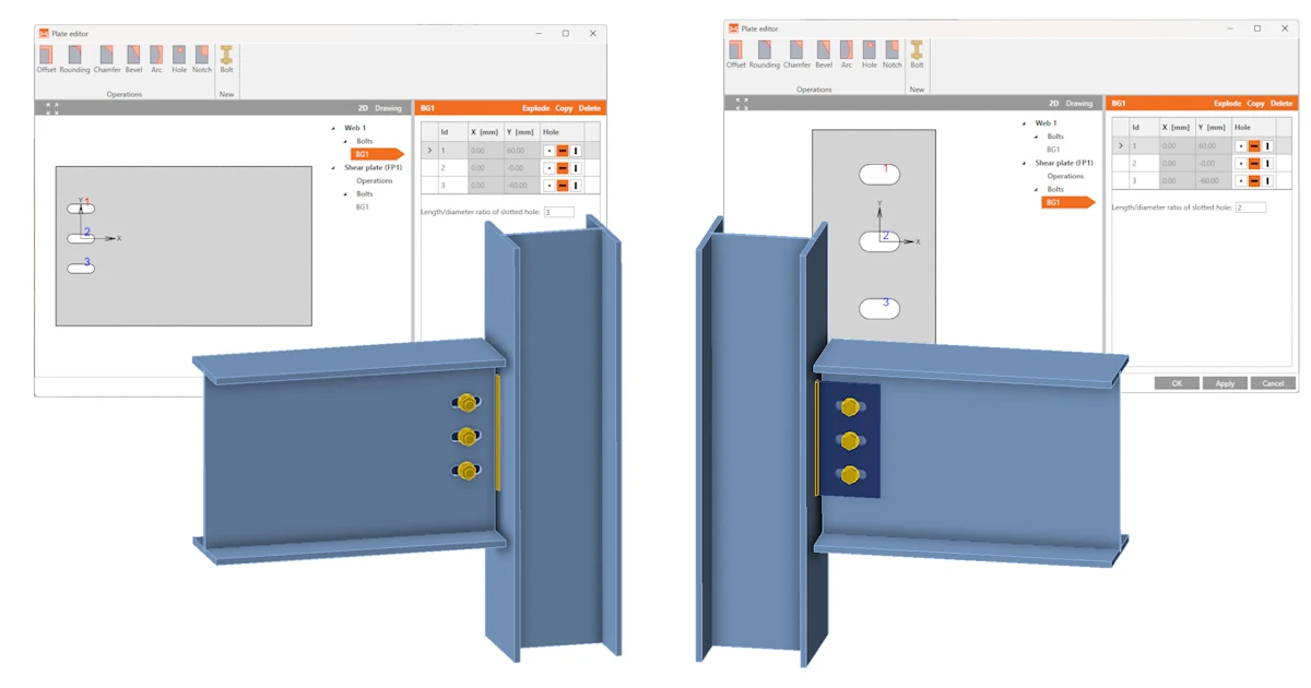
Variant 1: Slotted holes for a fin plate
Variant 2: Slotted holes for a beam web
The slotted holes can be assigned to multiple bolted plates.

Nevertheless, be aware that there must always be at least one plate with standard holes so that the numerical conditions are followed.
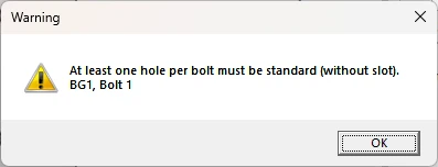
In some cases, it might happen the analysis does not run. 

From the general part of the Theoretical Background: Bolts in standard holes can transfer shear force in all directions, bolts in slotted holes have one direction excluded and can move in this selected direction freely.

To read more about the slotted holes in different standards, go to EN, AISC, CSA, AS, HKG, IS, GB, and SP Theoretical Backgrounds.

Custom sizes of the bolt assembly can be defined in the Material tab and saved to MPRL.

Take the latest version of IDEA StatiCa for a test drive today

Get 14 days of full access, completely free.

Check out IDEA StatiCa for free
Related articles

Release notes IDEA StatiCa 25.0
  • Steel
  • Concrete
  • v25.0
  • +3
  • Steel
  • Concrete
  • v25.0

Release notes

Release notes IDEA StatiCa 25.0

Read more
Using the plate Editor to shape a plate
  • Steel
  • Connection
  • Geometry
  • Manufacturing operations
  • Plates
  • +5
  • Steel
  • Connection
  • Geometry
  • Manufacturing operations
  • Plates

Knowledge base

Using the plate Editor to shape a plate

Read more
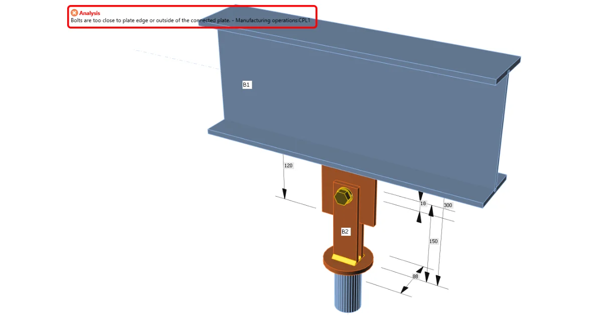
Bolts are too close to plate edge
  • Steel
  • Connection
  • Bolts
  • Manufacturing operations
  • Plates
  • +5
  • Steel
  • Connection
  • Bolts
  • Manufacturing operations
  • Plates

Knowledge base

Bolts are too close to plate edge

Read more
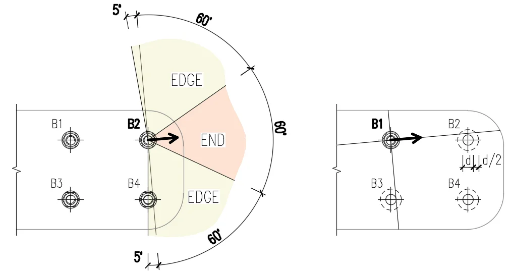
RN 20.1: Bolt bearing distances for Eurocode
  • Steel
  • Bolts
  • Manufacturing operations
  • Connection
  • EN (Eurocode)
  • +5
  • Steel
  • Bolts
  • Manufacturing operations
  • Connection
  • EN (Eurocode)

Knowledge base

Bolt bearing distances for Eurocode

Read more