Idea Statica
  • Steel
  • Concrete
  • BIM & Workflows
  • Support & Learning
  • Pricing
  • Company
  • Steel overview
  • Connection design
  • Member design
  • Parametric design
  • Steel case studies
  • Concrete overview
  • Walls and D-regions
  • Anchoring design
  • Concrete case studies
  • BIM Overview
  • Supported integrations
  • Checkbot
  • Viewer
  • APIs
  • Support Center
  • E-learning & certification
  • Blog
  • Downloads & Licensing
  • Plans
  • Free community tool
  • Enterprise customers
  • Students & educators
  • How much will you save?
  • About us
  • Contact
  • Research & development
  • Authorized resellers
  • Meet our customers
  • Career
  • Steel
    Steel overviewConnection designMember designParametric designSteel case studies
  • Concrete
    Concrete overviewWalls and D-regionsAnchoring designConcrete case studies
  • BIM & Workflows
    BIM OverviewSupported integrationsCheckbotViewerAPIs
  • Support & Learning
    Support CenterE-learning & certificationBlogDownloads & Licensing
  • Pricing
    PlansFree community toolEnterprise customersStudents & educatorsHow much will you save?
  • Company
    About usContactResearch & developmentAuthorized resellersMeet our customersCareer
14-Day Trial
14-Day Trial
  • Steel
  • Concrete
  • BIM & Workflows
  • Support & Learning
  • Pricing
  • Company

Subscribe to our newsletter

Company

  • About us
  • Partners
  • Careers
  • Patent

Resources

  • Customer projects
  • Case studies
  • Connection Library
  • Verification books

Legal

  • EULA
  • Privacy policy
  • California Privacy
  • TOS Viewer
  • Licensing

Help

  • Contact
  • Quote request
  • Resellers
  • Downloads
FacebookInstagramLinkedInYouTube

ยฉ IDEA StatiCa 2009-2026

Trusted and used worldwide by engineers, fabricators & consultants.

Support CenterKnowledge Base ArticlesHow to set position of bolts
How to set position of bolts
How to define preloaded bolts
Bolts and preloaded bolts connections
Prying and high tension force in bolts
Autodesign of bolts
Steel pins
Slotted holes for the selected plate
Distance between plates connected by a contact
Limitations of through bolts and hollow sections
Through bolts for hollow sections warning
Advanced anchoring design and anchors in Connection
How to set position of bolts
SteelConnection designKnowledge baseConnectionBolts

How to set position of bolts

This article is also available in
ENCZDEESFRITPTNLHUROKRPLTHTRVIZH

For operations that produce bolts (Bolt grid or contact, End plate, Fin plate, etc.) the input of bolts position and definition of bolt coordinates differ. When you hover your mouse over the text, you can read a tooltip describing the type of input, e.g., for Rows and Positions for the general bolt grid.

How to set position of bolts

Get familiar with the input of bolts for each operation by trying different values. You can always check the produced bolt grid dimensions in the 3D scene.

To display a 2D drawing with dimensions, go to the Editor of the operation and switch to the tab Drawing.

Input bolts position for End plate operation

Add the operation End plate and with the parameter Dimensions set the type end plate and thus bolt input.

Then input the symmetrical bolt positions by filling in the values of the Top layers and Left layers. For this operation, the values represent the distance from the outline of the cross-section toward the outside.

A multiple number of rows and columns of bolts can be specified using delimiters of two types:

Absolute delimiter ";" (a semi-colon) - distance measured from the outline of the cross-section (reference line)

Relative delimiter " " (space) - distanceย measured from the previous bolt row/column

E.g., the input of "40; 80; 120; 160; 200" is equal to "40 40 40 40 40" and also "4*40". You can also combine all delimiters, e.g., input "40; 80; 120 40 40".

You can check the bolt grid dimensions in the 3D scene.

How to set position of bolts

Move a single bolt within a bolt grid

You can change position or move a single bolt or a row of bolts in a bolt grid in the Editor. Select the manufacturing operation containing the bolt grid, then Explode the bolt group and change the coordinates of any bolt separately.

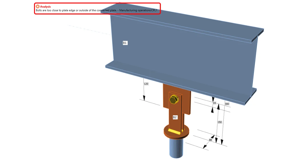
How to move one bolt within a bolt group

Related articles

Bolts are too close to plate edge
  • Steel
  • Connection
  • Bolts
  • Manufacturing operations
  • Plates
  • +5
  • Steel
  • Connection
  • Bolts
  • Manufacturing operations
  • Plates

Knowledge base

Bolts are too close to plate edge

Read more
A correct way how to define a stub
  • Steel
  • Connection
  • EN (Eurocode)
  • Cross-sections
  • Manufacturing operations
  • Modeling
  • AISC (USA)
  • +7
  • Steel
  • Connection
  • EN (Eurocode)
  • Cross-sections
  • Manufacturing operations
  • Modeling
  • AISC (USA)

Knowledge base

A correct way how to define a stub

Read more
Distance between plates connected by a contact
  • Steel
  • Connection
  • Contacts
  • Bolts
  • Plates
  • +5
  • Steel
  • Connection
  • Contacts
  • Bolts
  • Plates

Knowledge base

Distance between plates connected by a contact

Read more
How to model one bolt connection (Model type)
  • Steel
  • Connection
  • Bolts
  • Modeling
  • Geometry
  • +5
  • Steel
  • Connection
  • Bolts
  • Modeling
  • Geometry

Knowledge base

How to model a single bolt connection (Model type)

Read more