Idea Statica
  • Steel
  • Concrete
  • Support & Learning
  • Pricing
  • Company
  • Steel overview
  • Connection design
  • Member design
  • Parametric design
  • Steel case studies
  • Concrete overview
  • Walls and D-regions
  • Anchoring design
  • Concrete case studies
  • BIM Overview
  • Supported integrations
  • Checkbot
  • Viewer
  • APIs
  • Support Center
  • E-learning & certification
  • Blog
  • Downloads & Licensing
  • Plans
  • Free community tool
  • Enterprise customers
  • Students & educators
  • How much will you save?
  • About us
  • Contact
  • Research & development
  • Authorized resellers
  • Meet our customers
  • Career
  • Steel
    Steel overviewConnection designMember designParametric designSteel case studies
  • Concrete
    Concrete overviewWalls and D-regionsAnchoring designConcrete case studies
  • BIM OverviewSupported integrationsCheckbotViewerAPIs
  • Support & Learning
    Support CenterE-learning & certificationBlogDownloads & Licensing
  • Pricing
    PlansFree community toolEnterprise customersStudents & educatorsHow much will you save?
  • Company
    About usContactResearch & developmentAuthorized resellersMeet our customersCareer
14-Day Trial
14-Day Trial

Subscribe to our newsletter

Company

  • About us
  • Partners
  • Careers
  • Patent

Resources

  • Customer projects
  • Case studies
  • Connection Library
  • Verification books

Legal

  • EULA
  • Privacy policy
  • California Privacy
  • TOS Viewer
  • Licensing

Help

  • Contact
  • Quote request
  • Resellers
  • Downloads
FacebookInstagramLinkedInYouTube

ยฉ IDEA StatiCa 2009-2026

Trusted and used worldwide by engineers, fabricators & consultants.

Support CenterKnowledge Base ArticlesBolt bearing distances for Eurocode
Advanced analysis types for your steel structures
Bolts are too close to plate edge
Traffic lights for forces in bolts
Prying and high tension force in bolts
Bolt force distribution in end-plate beam-to-column connection
Bolt shear force calculated per shear plane
Bolt bearing distances for Eurocode
Warnings for welds and bolts connecting the same plates
Slip resistance check update according to SP 16
Detailing improvements for bolts and welds in Eurocode
Angle to the grain of the steel-to-timber connections
Filler plate (packing plate) recognition
Code-check of bolts and preloaded bolts (EN)
Code-check of bolts and preloaded bolts (AISC)
Code-check of bolts and preloaded bolts according to Canadian standards
Code-check of bolts and preloaded bolts according to Australian standards
Code-check of bolts and preloaded bolts according to Chinese standard
Code-check of bolts according to Hong Kong Code
Code-check of bolts and preloaded bolts according to Hong Kong Code
Code-check of bolts according to Indian standard
Code-check of preloaded bolts according to Indian standards
Code-check of bolts and preloaded bolts according to Russian standards
RN 20.1: Bolt bearing distances for Eurocode
SteelConnection designMember designKnowledge baseBolts

Bolt bearing distances for Eurocode

This article is also available in
ENCZDEESFRITPTNLHUROKRPLTHTRVIZH

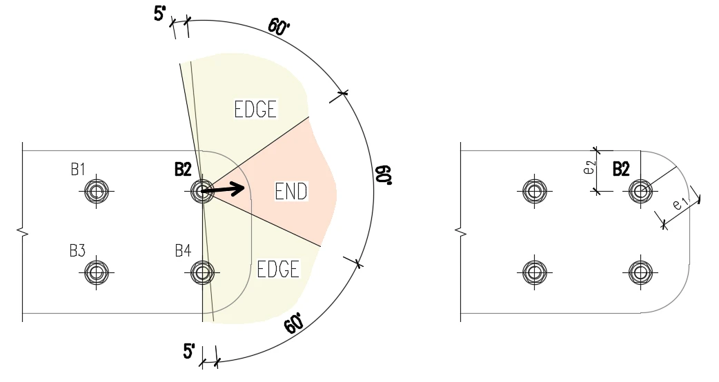
The new version brings an improved algorithm for calculating the bolt spacing (p1; p2), end (e1), and edge (e2) distances for the Eurocode bearing check. This improvement is mostly relevant for general plate geometries, plates with openings, cutouts, etc.

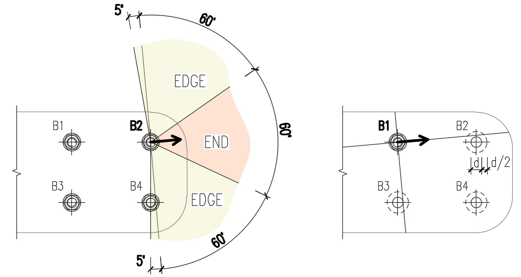
The algorithm reads the real direction of the resulting shear force vector in a given bolt and then calculates the distances needed for the bearing check.

The end (e1) and edge (e2) distances are determined by dividing the plate contour into three segments. The "end segment" is indicated by a 60ยฐ range in the direction of the force vector. The "edge segments" are defined by two 65ยฐ ranges perpendicular to the force vector. The shortest distance between a bolt and an edge in the relevant segment is then taken as an end, or edge distance.

The algorithm evaluates all plates connected by the boltโ€”the connecting plates (e.g., a splice plate), the member plates (e.g., a top flange), and the shortest distance is used.
Bolt bearing distances (EN)

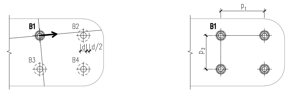
The spacing distances between bolt holes (p1; p2) are determined by virtually enlarging the surrounding bolt holes by half their diameter, then drawing two lines in the direction and perpendicular to the shear force vector. When these lines intersect with virtually enlarged bolt holes, then the distances to these bolts are considered as p1 and p2 in the calculation.

If the lines don't intersect with the visually closest bolt (even though the line misses the bolt closely), this bolt is neglected. If the lines don't intersect with any bolt, an infinite value is used.
Bolt bearing distances (EN)

Available in Expert and Enhanced editions.
Related articles

Bolted steel connection
  • Steel
  • Bolts
  • Connection
  • +3
  • Steel
  • Bolts
  • Connection

Blog post

Bolts and bolted connections

Read more
The forces in bolts, including prying forces, are determined by finite element analysis. The bolt resistances are checked by code provisions. Structural design of bolted steel connections.
  • Steel
  • Connection
  • CBFEM
  • Bolts
  • EN (Eurocode)
  • +5
  • Steel
  • Connection
  • CBFEM
  • Bolts
  • EN (Eurocode)

Knowledge base

Code-check of bolts and preloaded bolts (EN)

Read more
How to define pre-loaded bolts
  • Steel
  • Connection
  • AISC (USA)
  • Bolts
  • Contacts
  • EN (Eurocode)
  • +6
  • Steel
  • Connection
  • AISC (USA)
  • Bolts
  • Contacts
  • EN (Eurocode)

Knowledge base

How to define preloaded bolts

Read more
Prying and high tension force in bolts
  • Steel
  • Connection
  • CBFEM
  • Bolts
  • Stress/strain
  • +5
  • Steel
  • Connection
  • CBFEM
  • Bolts
  • Stress/strain

Knowledge base

Prying and high tension force in bolts

Read more