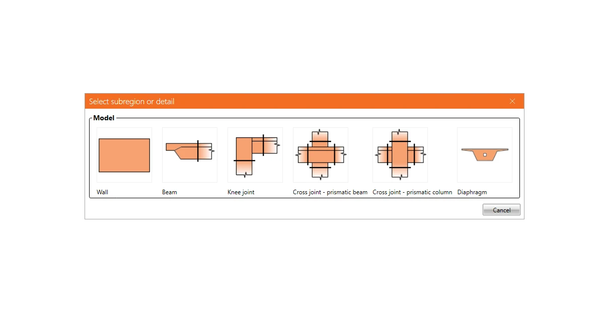


Wall
The wall is the most general entity that can be defined in your model. There are various cases for which you can use this detail. Now, it's time to explain how.
First, let's talk about the shape of the element. The wall's shape can be defined as:
- Rectangular
Using this option, all you need to do is to set the element's width, height, thickness, and, if necessary, offset in X direction related to the top left and right corner.
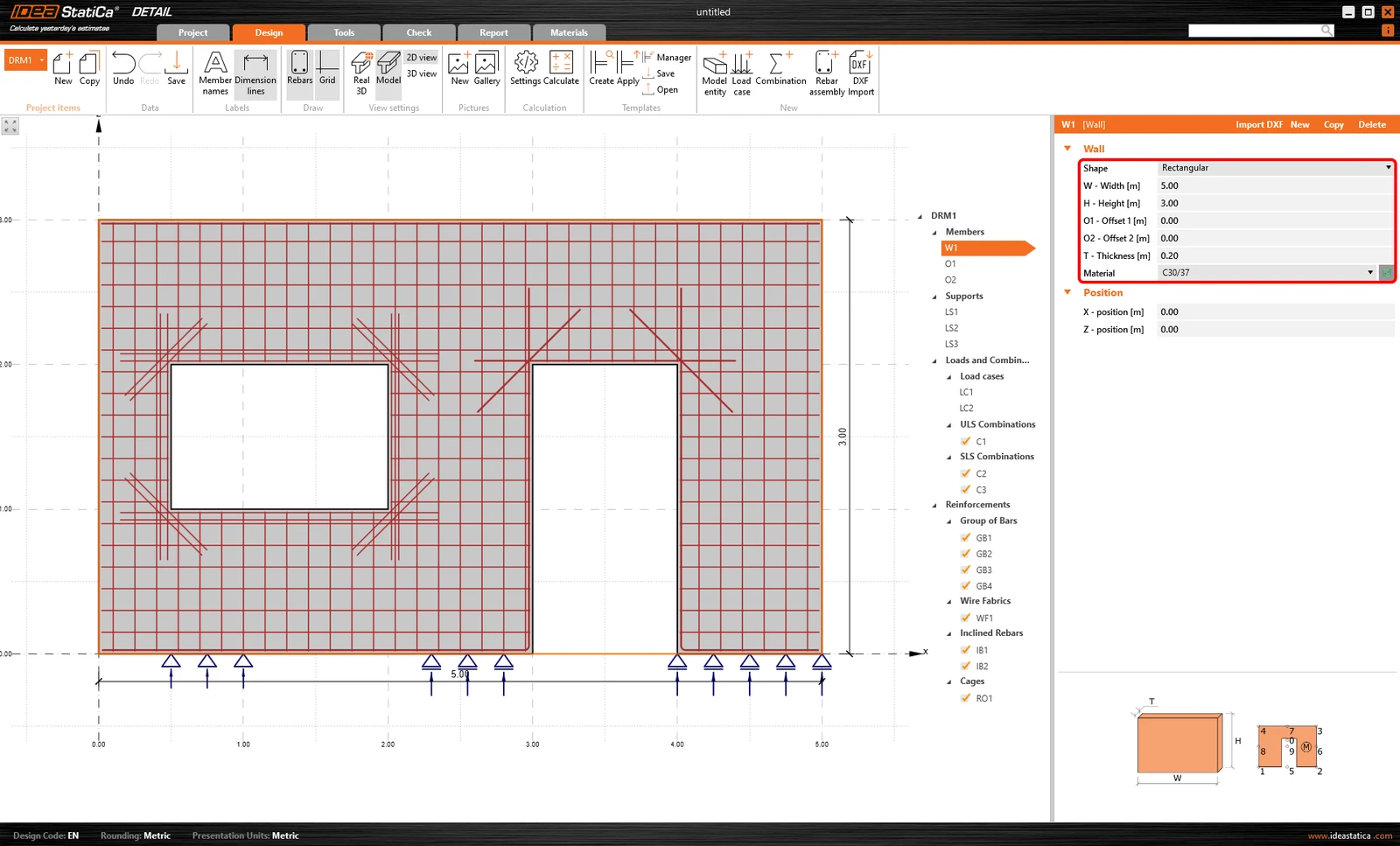
- Polygon
If you need a more complex topology, the Polygon shape is the way. The geometry can be defined by selecting the Edit shape button in the data window, and then in the wizard using coordinates in X and Z directions related to the global coordinate system. You can add new rows, or delete the existing ones using the right-click into the coordinates table.
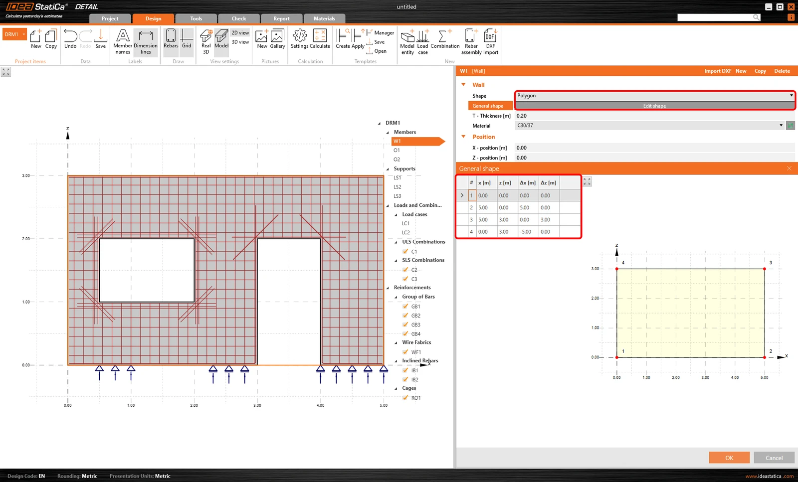
- Import DXF
In case of having a complex shape of the structure or already finished drawings, you can use the import from the DXF file functionality to have the geometry defined quickly.
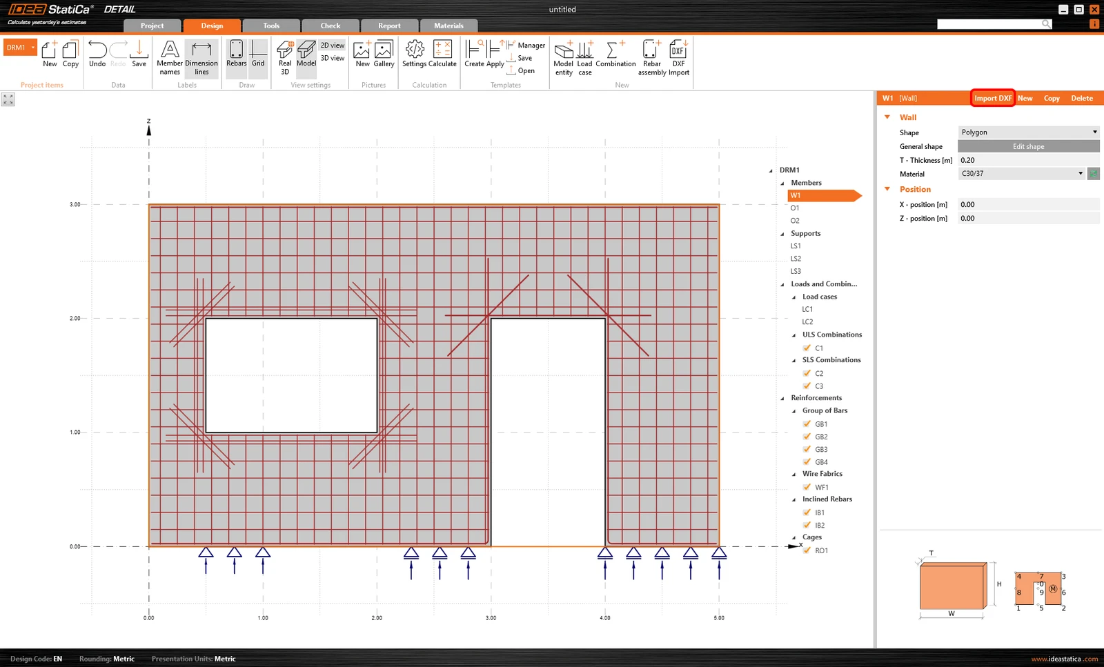
Simply click on the Import DXF button, pick the file from your storage, and start selecting the structure's outline. It can be done by choosing the lines individually in the main graphic window, or just a single line and then clicking the Consecutive button from the top ribbon.
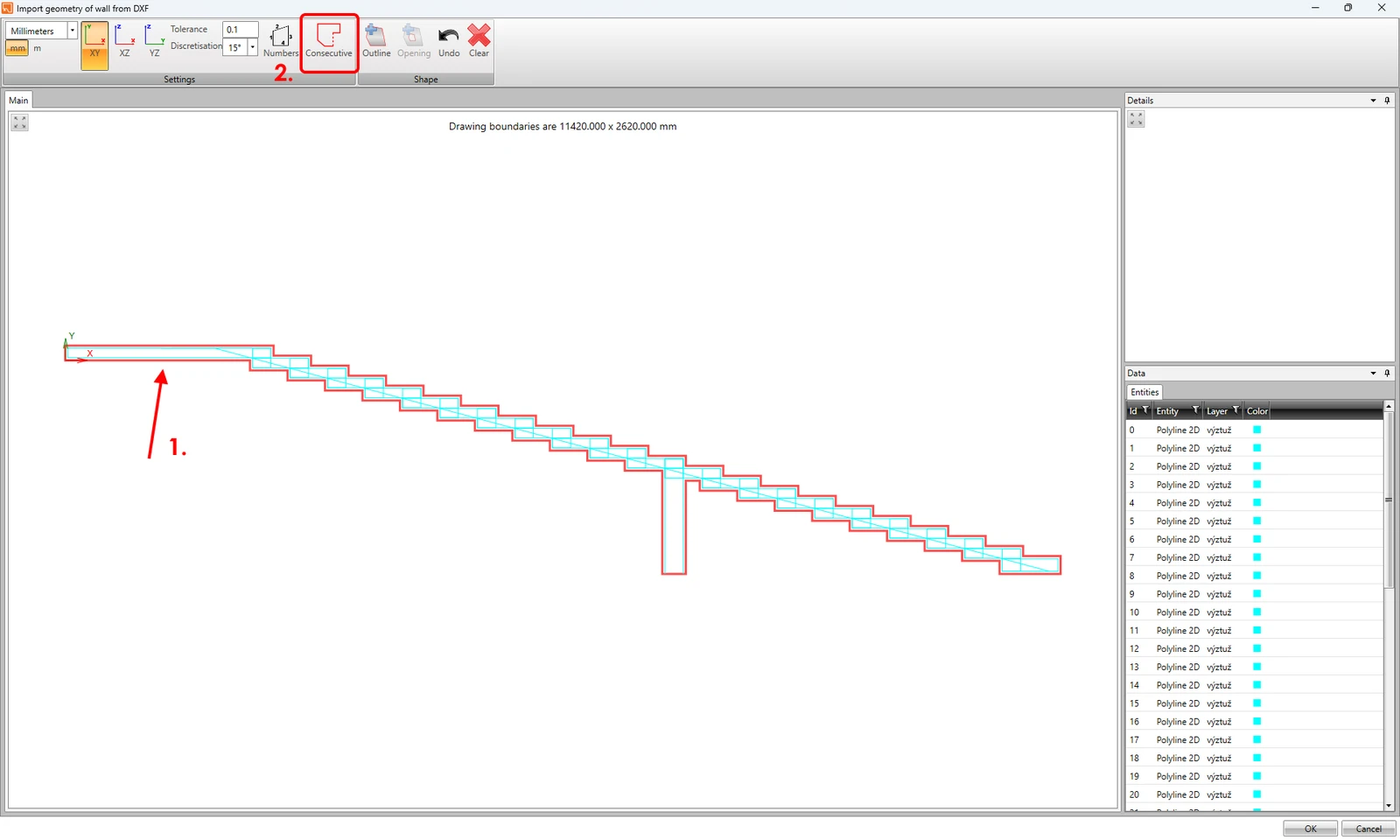
In the wizard, you can use the full potential of the functionalities in the top ribbon - it is possible to change the units, distinguish three planes - XY, XZ, and YZ in which the drawing is done, set some tolerance and discretization of curved lines, entities numbers, and add openings directly. On top of that, when you make a mistake, you can undo the steps, and clear the selection.
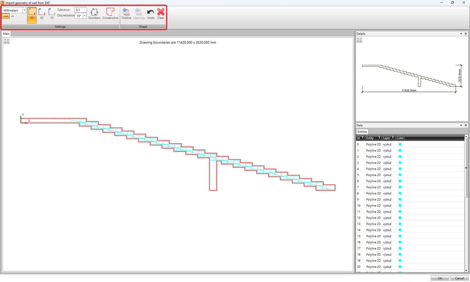
Moreover, you can even import the geometry together with the reinforcement!
Now, let's sum up the most important information you need to know for proper wall element definition.
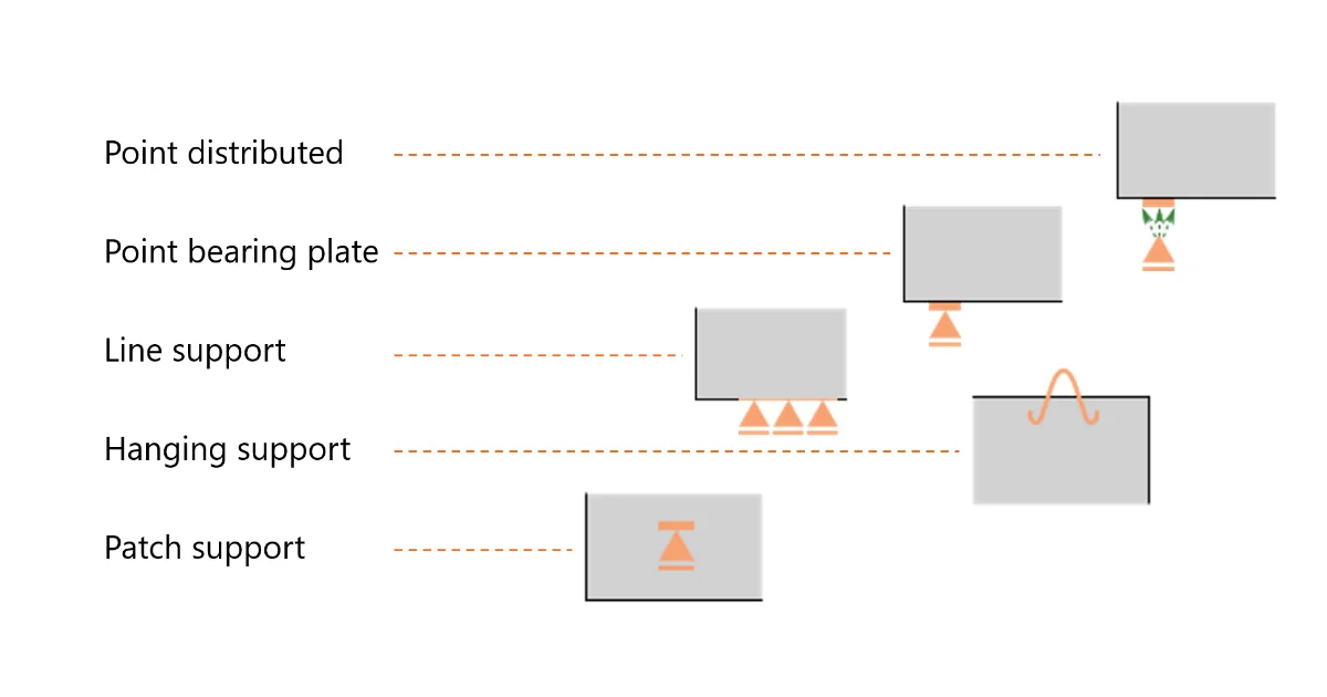
- All types of supports and transfer devices can be used for this geometry type.
- It is not possible to add a trimmed end of the wall, the structure must be defined as a whole.
- All types of openings can be applied.
- And last but not least, the wall entity must have a constant thickness.
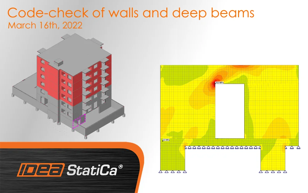
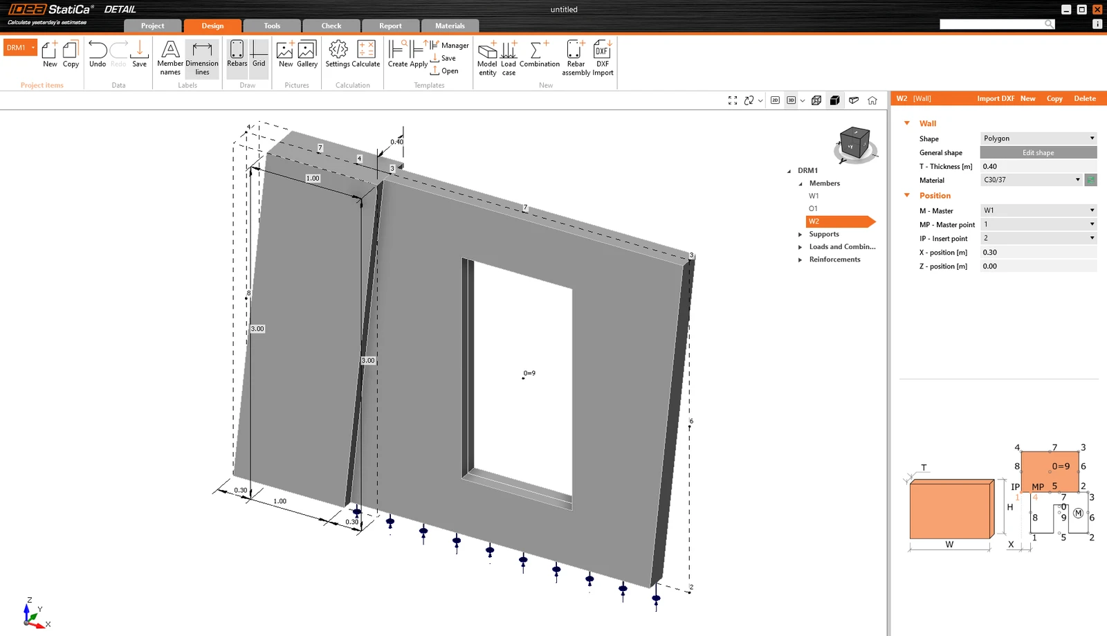
The whole model can be made up of several separate elements. The software will automatically connect them. The joint between the walls must be free of gaps. Moreover, it is possible to define different thicknesses for each wall element used in the project. See the example in the image below.
Beam
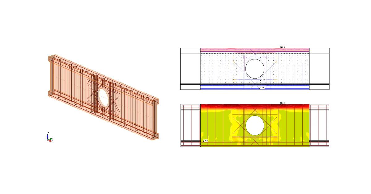
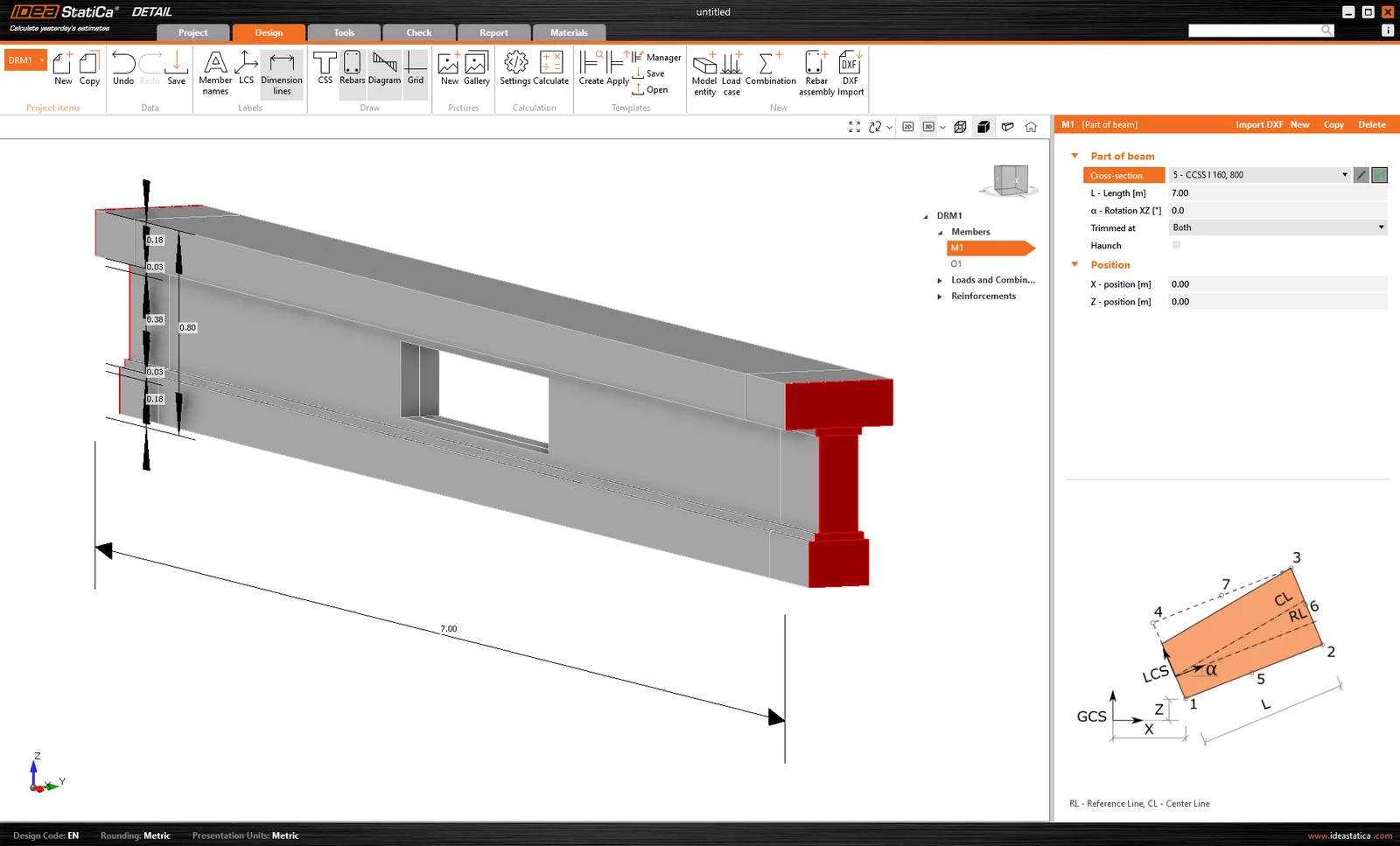
This element can be used for various types of beams. It is up to you whether you need to model and analyze the whole beam or just want to focus on a specific area - discontinuity region using the trimmed end option.
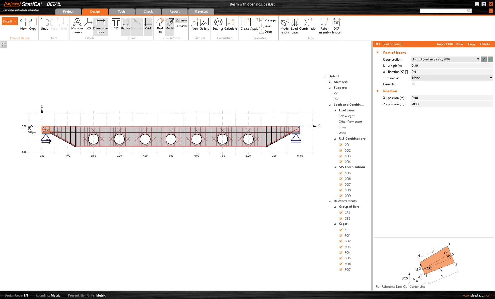
Example of a whole saddle beam with openings
Let's say you have already designed and checked the reinforcement in the B-regions, and you want to focus on the discontinuity regions of the beam only, so you won't spend additional time modeling the whole beam. No problem! In this case, it is recommended to model the trimmed beam.
The beam can be trimmed at:
- Beginning
- End
- Or both the beginning and end at the same time
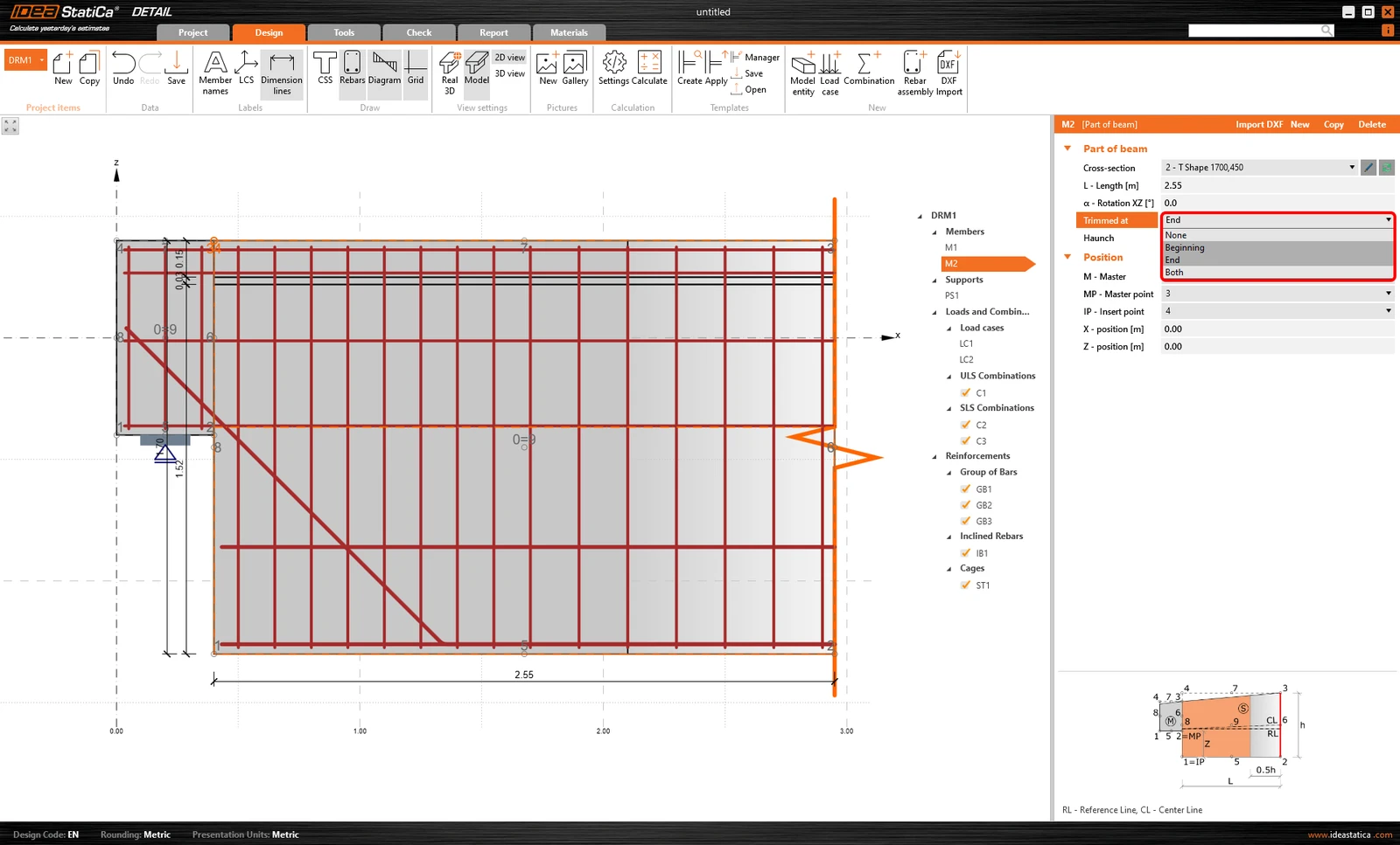
Example of a beam with the trimmed end
When modeling a beam, you can select one of the pre-defined cross-sections from the library.
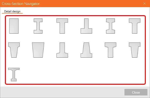
The beam is defined as a 2D element. The cross-section of the beam is used only to set the proper thicknesses.
Let's check the summary for beam elements:
- All types of supports and transfer devices can be used for this geometry type.
- The beam can be trimmed at the beginning, end, or both the beginning and end.
- All types of openings can be applied.
- The structure can have haunches - just select the checkbox in the data window and set the parameters.
Knee joint
A knee joint is a type of frame joint - basically the most commonly used D-region. Sometimes, they can be underestimated in the design. However, it is important to pay attention to them. And it can be easy when you have a powerful tool such as the IDEA StatiCa Detail application.
What's important to know?
- As in the beam element case, also the knee joint is defined using a cross-section selected from the library.
- Compared to wall and beam types, you can't set supports. Only the usage of trimmed or free ends is allowed in this case. Nevertheless, all types of load transferring devices can be applied to the structure.
- All types of openings can be applied.
- The structure can have haunches - just select the checkbox in the data window and set the parameters. On top of that, the members can be inclined by the wanted angle.
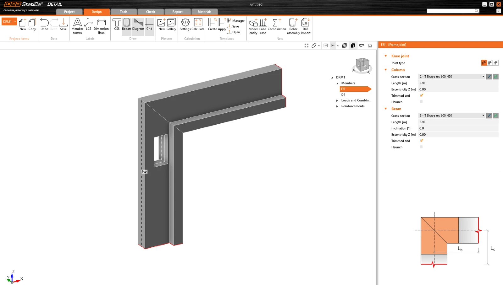
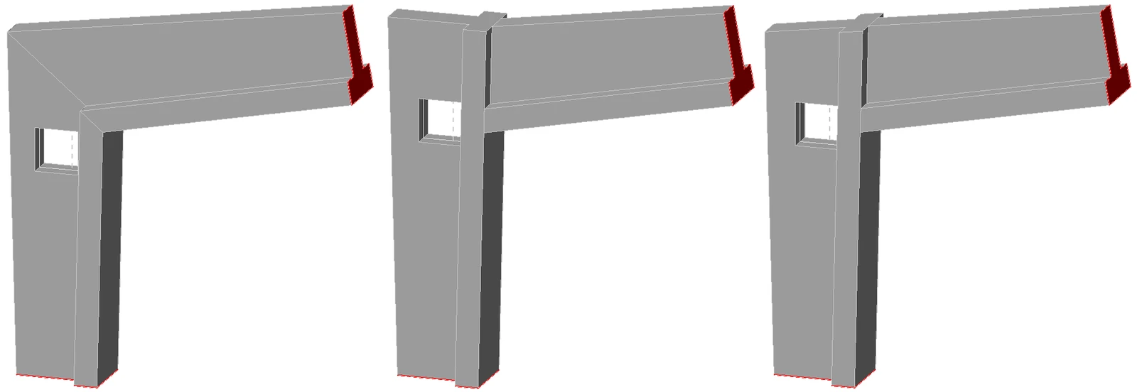
The geometry of the knee joint may vary. In the Detail app, you can select from three options to define the most suitable one.
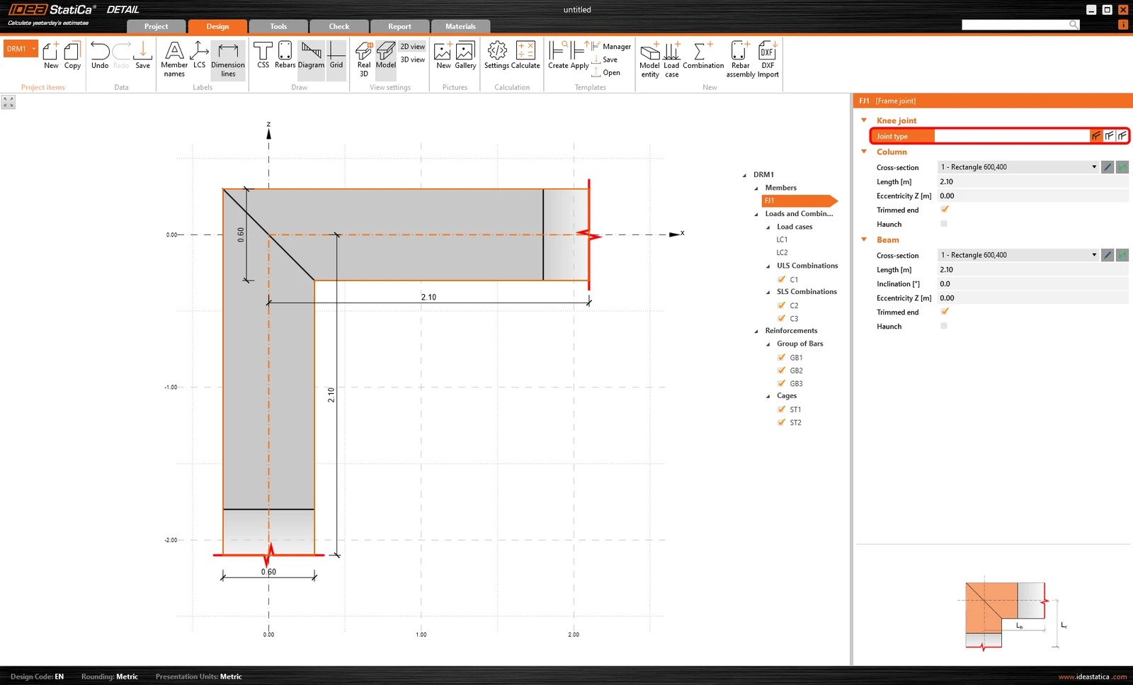
To see it in the action, check the image below. These three structures were created by using the same settings, only with different joint types.
Cross joint
This option is identical to the knee joint. For the characteristics, see the previous paragraph.
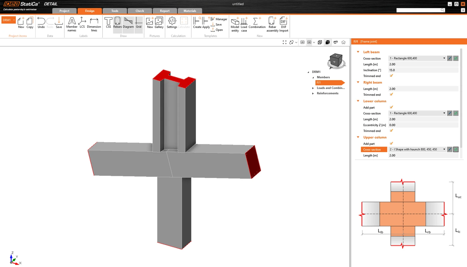
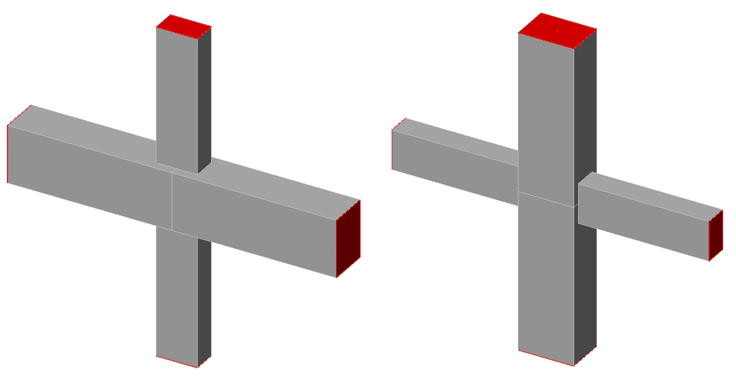
There are two types of Cross joints - prismatic beam or prismatic column. The difference is shown in the image below.
Diaphragm
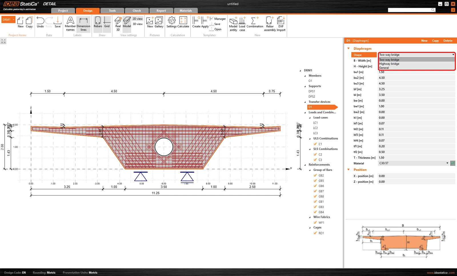
Diaphragms are exactly the same as walls in terms of the element's definition. For more information, please see the Wall paragraph.
There are three ways to define the shape:
- Two-way bridge
- Highway bridge
- And General - by polyline or imported from the DXF file
It is important to mention that these details (subregions) can be divided into two groups. The difference between them is in the element's thickness definition:
- Walls and Diaphragms - constant thickness
- Beams and Joints - thickness defined by a cross-section
Please be aware that all geometry types mentioned above are in the software considered as 2D elements, thus can transfer only in plane loads, and out of plane forces must be neglected.
Try IDEA StatiCa for free
Start your trial today and enjoy 14-days of full access and services free of charge.
Start free trial