Idea Statica
  • Steel
  • Concrete
  • BIM & Workflows
  • Support & Learning
  • Pricing
  • Company
  • Steel overview
  • Connection design
  • Member design
  • Parametric design
  • Steel case studies
  • Concrete overview
  • Walls and D-regions
  • Anchoring design
  • Concrete case studies
  • BIM Overview
  • Supported integrations
  • Checkbot
  • Viewer
  • APIs
  • Support Center
  • E-learning & certification
  • Blog
  • Downloads & Licensing
  • Plans
  • Free community tool
  • Enterprise customers
  • Students & educators
  • How much will you save?
  • About us
  • Contact
  • Research & development
  • Authorized resellers
  • Meet our customers
  • Career
  • Steel
    Steel overviewConnection designMember designParametric designSteel case studies
  • Concrete
    Concrete overviewWalls and D-regionsAnchoring designConcrete case studies
  • BIM & Workflows
    BIM OverviewSupported integrationsCheckbotViewerAPIs
  • Support & Learning
    Support CenterE-learning & certificationBlogDownloads & Licensing
  • Pricing
    PlansFree community toolEnterprise customersStudents & educatorsHow much will you save?
  • Company
    About usContactResearch & developmentAuthorized resellersMeet our customersCareer
14-Day Trial
14-Day Trial
  • Steel
  • Concrete
  • BIM & Workflows
  • Support & Learning
  • Pricing
  • Company

Subscribe to our newsletter

Company

  • About us
  • Partners
  • Careers
  • Patent

Resources

  • Customer projects
  • Case studies
  • Connection Library
  • Verification books

Legal

  • EULA
  • Privacy policy
  • California Privacy
  • TOS Viewer
  • Licensing

Help

  • Contact
  • Quote request
  • Resellers
  • Downloads
FacebookInstagramLinkedInYouTube

© IDEA StatiCa 2009-2026

Trusted and used worldwide by engineers, fabricators & consultants.

Support CenterKnowledge Base ArticlesSteel joint analysis model
How to define correct load position (Forces in)
Equilibrium and supporting member
Key insights into constraints, member length and GMNA vs MNA analysis
When to use a stiffening member?
How to model a single bolt connection (Model type)
Model type - additional boundary condition
Shear force position input and visualization
Default member length in Connection
The right LCS (local coordinate system) orientation
How to use a rod (solid bar) member
Relative positions of members
Steel joint analysis model
Structural design of welded and bolted connections. The analysis model is generated automatically based on the inputs from manufacturing operations. IDEA StatiCa - structural analysis software.
SteelConnection designKnowledge baseConnectionAISC (USA)

Steel joint analysis model

This article is also available in
ENCZDEESFRITPTNLHUROKRPLTHTRVIZH

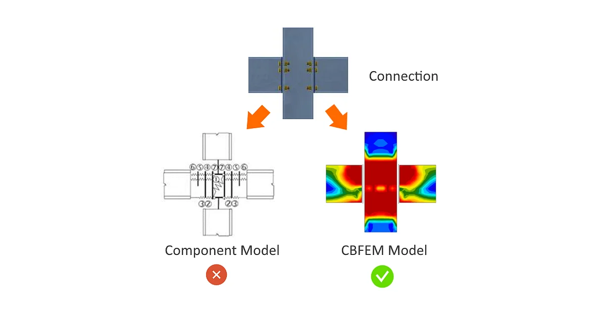
The CBFEM method (Component Based Finite Element Model) enables fast analysis of joints of several shapes and configurations. The model consists of members to which the load is applied and manufacturing operations (including stiffening members), which serve to connect members to each other. Members must not be confused with manufacturing operations because their cut edges are connected via rigid links to the connection node, so they are not deformed properly if used instead of manufacturing operations (stiffening members).

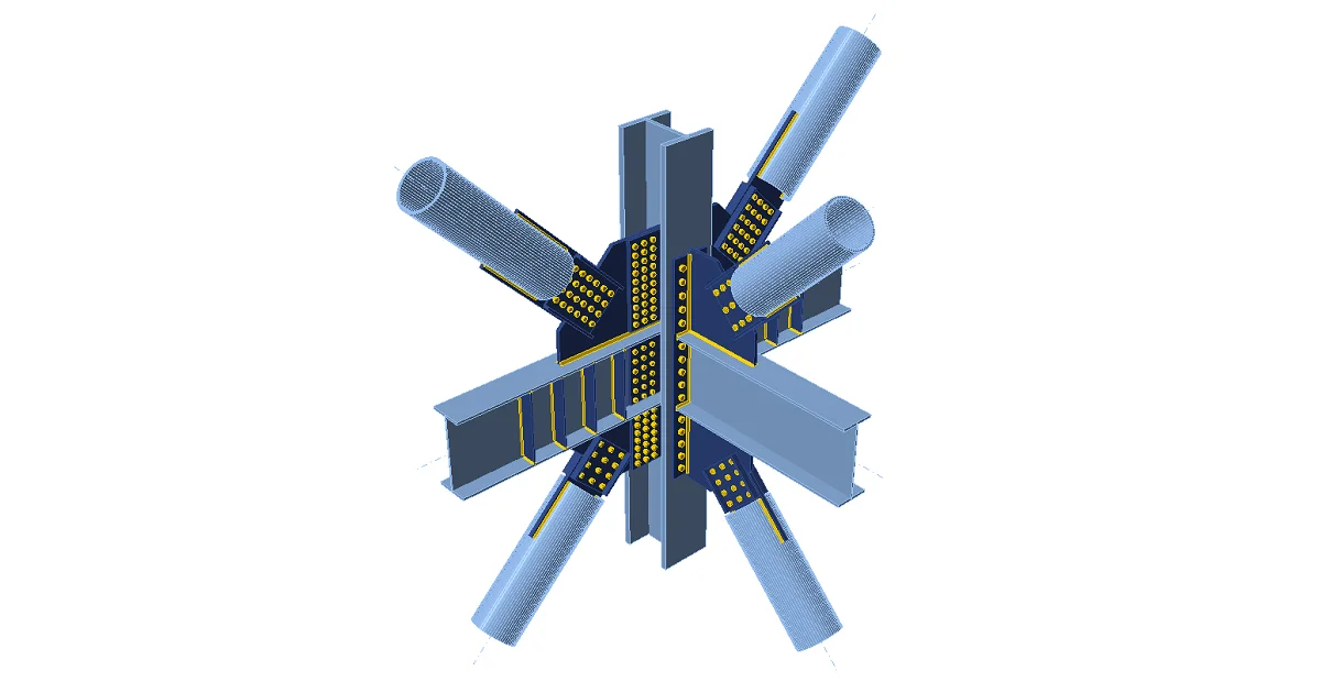
The analyzed FEM model is generated automatically. The user does not create the FEM model; instead, the user only creates the connection model using manufacturing operations – see the figure.
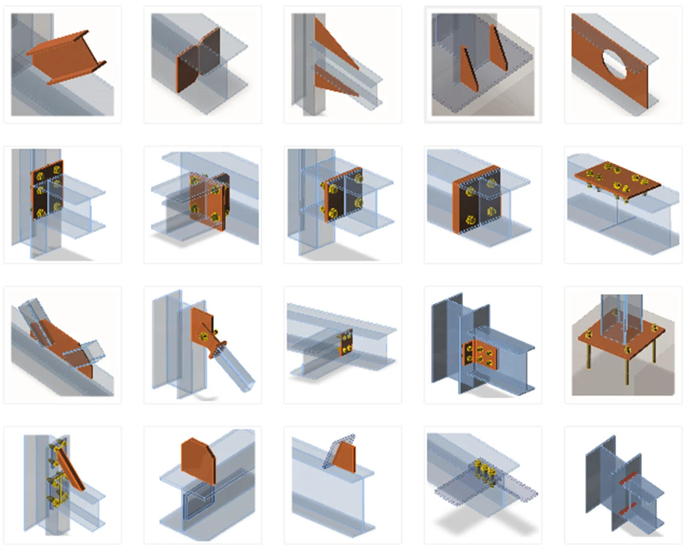
Structural design of welded and bolted connections. The analysis model is generated automatically based on the inputs from manufacturing operations. IDEA StatiCa - structural analysis software.

Manufacturing operations/items which can be used to construct the joint

Each manufacturing operation adds new items to the connection – cuts, plates, bolts, welds.

Bearing members and supports

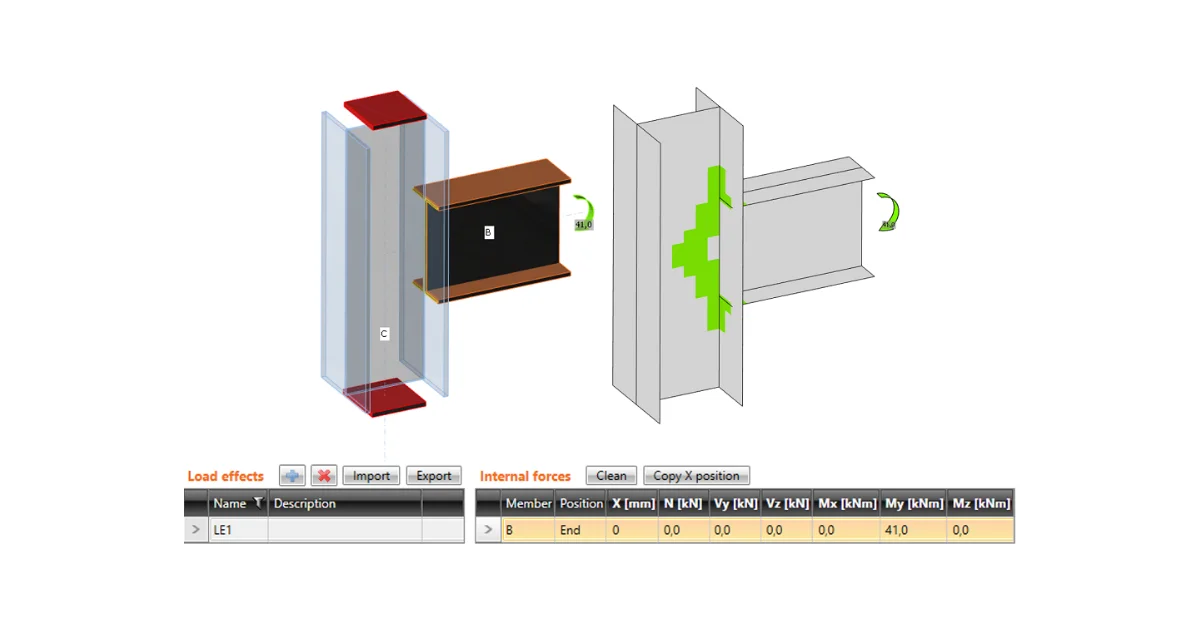
One member of the joint is always set as “bearing”. All other members are “connected”. The bearing member can be chosen by the designer. The bearing member can be “continuous” or “ended” in the joint. “Ended” members are supported on one end, and “continuous” members are supported on both ends.

Connected members can be of several types, according to the load which the member can take:

  • Type N-Vy-Vz-Mx-My-Mz – member is able to transfer all 6 components of internal forces
  • Type N-Vy-Mz – member is able to transfer only loading in XY plane – internal forces N, Vy, Mz
  • Type N-Vz-My – member is able to transfer only loading in XZ plane – internal forces N, Vz, My
  • Type N-Vy-Vz – member is able to transfer only normal force N and shear forces Vy and Vz
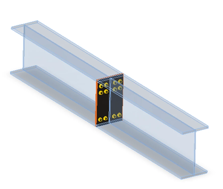
Plate to plate connection transfers all components of internal forces
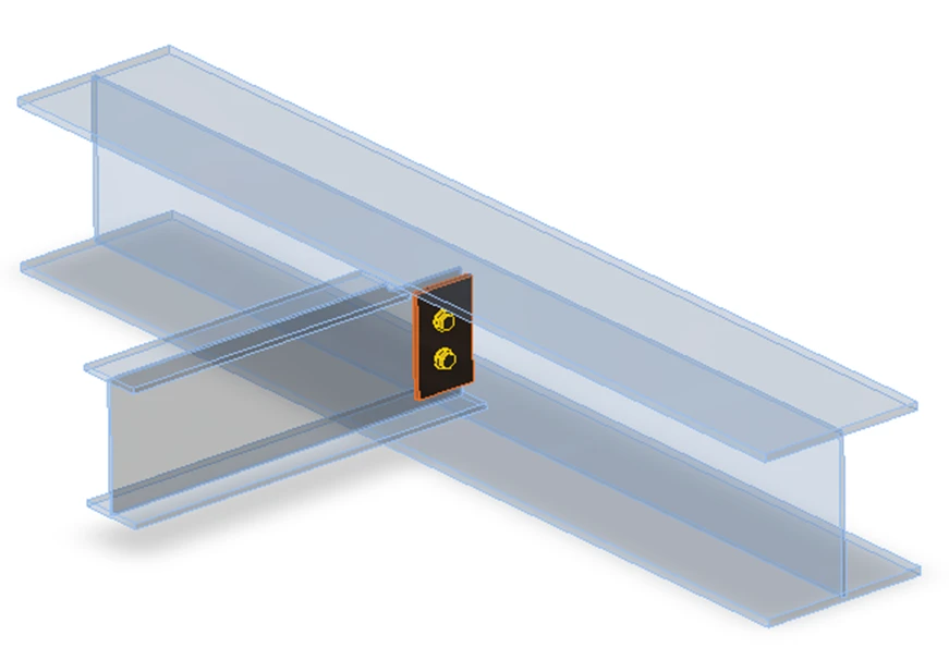
Fin plate connection can transfer only loads in XZ plane – internal forces N, Vz, My
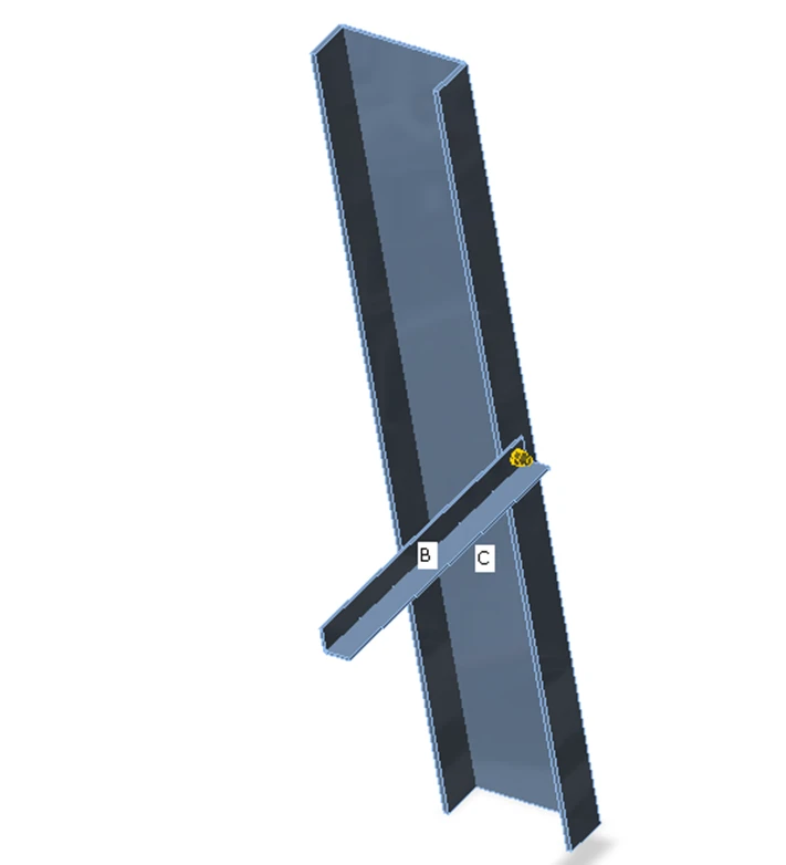
Gusset connection – connection of truss member can transfer only axial force N and shear forces Vy and Vz

Each joint is in the state of equilibrium during the analysis of the frame structure. If the end forces of the individual members are applied to detailed CBFEM model, the state of equilibrium is met too. Thus, it would not be necessary to define supports in the analysis model. However, for practical reasons, the support resisting all translations is defined in the first end of the bearing member. It does influence neither the state of stress nor the internal forces in the joint, only the presentation of deformations.

Appropriate support types respecting the type of the individual members are defined at the ends of the connected members to prevent the occurrence of unstable mechanisms.

The default length of each member is twice its height. The length of a member should be at least 1Ă— the height of the member after the last manufacturing operation (weld, opening, stiffener etc.) due to the correct deformations after the rigid links connecting the cut end of a member to the connection node.
Related articles

IDEA StatiCa Connection – Structural design of steel connections
  • Steel
  • Connection
  • EN (Eurocode)
  • AISC (USA)
  • AS (Australia)
  • CSA (Canada)
  • IS (India)
  • GB (China)
  • HKG (Hong Kong)
  • SP 16 (Russia)
  • CBFEM
  • +11
  • Steel
  • Connection
  • EN (Eurocode)
  • AISC (USA)
  • AS (Australia)
  • CSA (Canada)
  • IS (India)
  • GB (China)
  • HKG (Hong Kong)
  • SP 16 (Russia)
  • CBFEM

Theoretical background

IDEA StatiCa Connection – Structural design of steel connections

Read more
Structural design of welded and bolted connections. The loads in any node in the structural model need to be in equilibrium. Any unbalanced forces are taken by supports. IDEA StatiCa - structural analysis software.
  • Steel
  • Connection
  • AISC (USA)
  • AS (Australia)
  • CSA (Canada)
  • EN (Eurocode)
  • IS (India)
  • GB (China)
  • HKG (Hong Kong)
  • CBFEM
  • SP 16 (Russia)
  • Equilibrium
  • +12
  • Steel
  • Connection
  • AISC (USA)
  • AS (Australia)
  • CSA (Canada)
  • EN (Eurocode)
  • IS (India)
  • GB (China)
  • HKG (Hong Kong)
  • CBFEM
  • SP 16 (Russia)
  • Equilibrium

Knowledge base

Node equilibrium in the 3D FEM model

Read more
What is the CBFEM - Component-based finite element method
  • Steel
  • Connection
  • AISC (USA)
  • CBFEM
  • EN (Eurocode)
  • +5
  • Steel
  • Connection
  • AISC (USA)
  • CBFEM
  • EN (Eurocode)

FAQ

What is the CBFEM?

Read more