Idea Statica
  • Steel
  • Concrete
  • Support & Learning
  • Pricing
  • Company
  • Steel overview
  • Connection design
  • Member design
  • Parametric design
  • Steel case studies
  • Concrete overview
  • Walls and D-regions
  • Anchoring design
  • Concrete case studies
  • BIM Overview
  • Supported integrations
  • Checkbot
  • Viewer
  • APIs
  • Support Center
  • E-learning & certification
  • Blog
  • Downloads & Licensing
  • Plans
  • Free community tool
  • Enterprise customers
  • Students & educators
  • How much will you save?
  • About us
  • Contact
  • Research & development
  • Authorized resellers
  • Meet our customers
  • Career
  • Steel
    Steel overviewConnection designMember designParametric designSteel case studies
  • Concrete
    Concrete overviewWalls and D-regionsAnchoring designConcrete case studies
  • BIM OverviewSupported integrationsCheckbotViewerAPIs
  • Support & Learning
    Support CenterE-learning & certificationBlogDownloads & Licensing
  • Pricing
    PlansFree community toolEnterprise customersStudents & educatorsHow much will you save?
  • Company
    About usContactResearch & developmentAuthorized resellersMeet our customersCareer
14-Day Trial
14-Day Trial

Subscribe to our newsletter

Company

  • About us
  • Partners
  • Careers
  • Patent

Resources

  • Customer projects
  • Case studies
  • Connection Library
  • Verification books

Legal

  • EULA
  • Privacy policy
  • California Privacy
  • TOS Viewer
  • Licensing

Help

  • Contact
  • Quote request
  • Resellers
  • Downloads
FacebookInstagramLinkedInYouTube

© IDEA StatiCa 2009-2026

Trusted and used worldwide by engineers, fabricators & consultants.

Support CenterKnowledge Base ArticlesWhen to use a stiffening member?
How to define correct load position (Forces in)
Equilibrium and supporting member
Key insights into constraints, member length and GMNA vs MNA analysis
When to use a stiffening member?
How to model a single bolt connection (Model type)
Model type - additional boundary condition
Shear force position input and visualization
Default member length in Connection
The right LCS (local coordinate system) orientation
How to use a rod (solid bar) member
Relative positions of members
Steel joint analysis model
When to use a stiffening member?
Creating an U-shaped clip connection
How to design a haunch
When to use a stiffening member in IDEA StatiCa Connection?
Connection designSteelMember designKnowledge baseConnection

When to use a stiffening member?

This article is also available in
ENCZDEESFRITPTNLHUROKRPLTHTRVIZH

Stiffening members are used to simulate a joint element with cross-sections. This helps you to design any needed topology.

The fundamental difference between a standard member and a stiffening member is that we can not input any internal forces and supports on stiffening members. We use standard members only if we need to apply load/constraint on them. 

A stiffening member is not part of the original FEA 1D member analysis model; it only fills in the joint's missing parts. Another feature of a stiffening member, contrary to a standard member, is that you can have it at any length you need.

To add a stiffening member, click on new Operation and select  a new manufacturing operation:
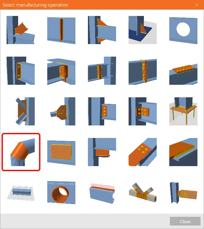
Operation Stiffening member

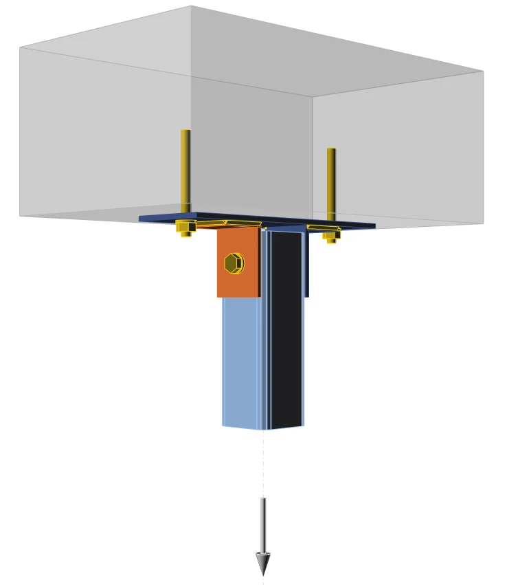
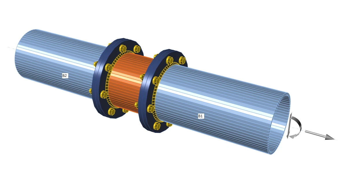
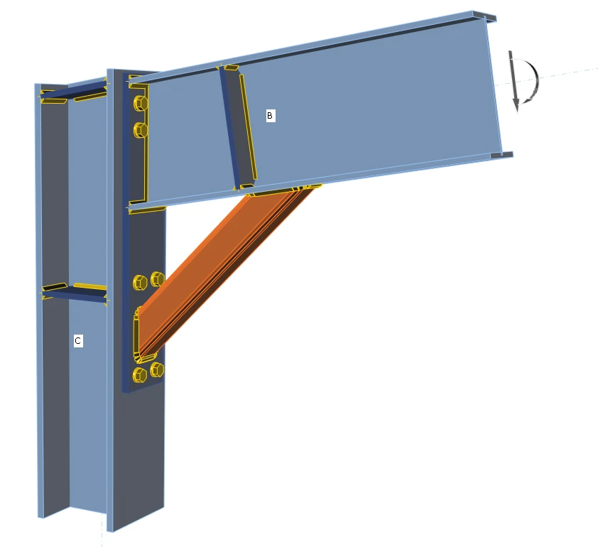
Typical examples where the stiffening member operation is used are, e.g., the intermediate part of the connected continuous member or strut support between a column and a beam or anchoring via cleats.
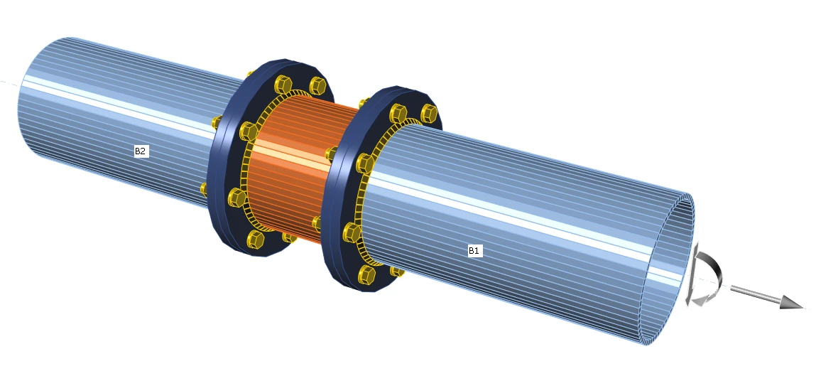
Tubular joint
Stiffener

The summary of the stiffening member operation and the procedure to create an example with a stiffening member is demonstrated in the following video.

Try IDEA StatiCa for free

Start your trial today and enjoy 14 days of full access and services free of charge.

Start free trial
Related articles

Modeling tips&tricks - US
  • Steel
  • Connection
  • Modeling
  • AISC (USA)
  • +4
  • Steel
  • Connection
  • Modeling
  • AISC (USA)

Webinar

Modeling tips&tricks - US

Read more
 Create advanced connection topologies and connection types
  • Steel
  • Connection
  • Geometry
  • Modeling
  • Plates
  • Cross-sections
  • +6
  • Steel
  • Connection
  • Geometry
  • Modeling
  • Plates
  • Cross-sections

Knowledge base

Creating an U-shaped clip connection

Read more
How to create and use a custom cross-section
  • Steel
  • Connection
  • AISC (USA)
  • Geometry
  • Cross-sections
  • DXF
  • EN (Eurocode)
  • Modeling
  • +8
  • Steel
  • Connection
  • AISC (USA)
  • Geometry
  • Cross-sections
  • DXF
  • EN (Eurocode)
  • Modeling

Knowledge base

How to create and use a custom cross-section

Read more