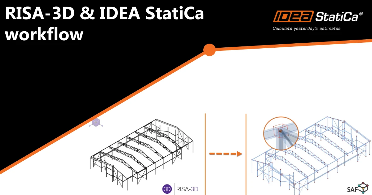


Before you start: Prepare the RISA-3D model
Two model conditions must be set in RISA-3D before exporting. If either is missed, the forces will not import or will not balance at the connections. The two conditions are set below:
1. Set the global vertical axis to Z
RISA-3D uses Y as the vertical axis by default, while the SAF format and IDEA StatiCa use Z. Before exporting, change the global vertical axis from Y to Z. This updates only the Global Coordinate System (GCS), not the
Local Coordinate System (LCS).
Note: Changing GCS from Y to Z can affect loading direction, always go back and verify loads are correct.

2. Split members at every connection node
Any member that runs continuously *through* a node where a connection will be designed must be split into separate members, each terminating at that node.
RISA's member section-force results are reported at points along each member; if a connection node falls partway along a continuous member rather than at its end, the forces at that node cannot be reconstructed accurately, and the connection will not reach equilibrium in Checkbot.
RISA-3D can perform this split automatically for the entire model:
- Disable physical members. Select the entire project, then select the option to view only member properties, and uncheck Physical Member. This allows the member to be subdivided at intermediate nodes rather than treated as a single continuous element.
- Run a full model merge. Go to Modify → Model Merge. RISA will automatically insert nodes at all member intersections and split the members accordingly, so that every member terminates at the nodes it meets.
After the merge, every member that frames into a connection node will have that node as its start (I-end) or end (J-end) rather than as an interior point, which is what allows the forces to balance correctly once imported into Checkbot.
RISA - IDEA StatiCa full integration
1. Export model and forces from RISA-3D
Two files are exported from the same solved RISA-3D model.
1a. Export the SAF file (geometry) - This file contains the model geometry, members, cross sections, and
materials.
- File → Export → SAF

1b. Export the Member Section Forces file (results) - This file contains the analysis result forces for each member and load combination.
- File → Export → Excel File → Export an Individual RISA Result Section → Member Forces

Notes: This SAF-based integration is developed and maintained by RISA. IDEA StatiCa is not responsible for maintaining the SAF files or their information. All technical requirements and questions should be addressed directly to RISA.
2. Combine the files with the RISA-IDEA SAF Integrator
Download and install the RISA-IDEA SAF Integrator app:
RISA-IDEA SAF Integrator download
2a. Launch the RISA-IDEA SAF Integrator.
- Step 1 field — RISA SAF file: Browse to the SAF file from Step 1a.
- Step 2 field — Member Section Forces file: Browse to the file from Step 1b.
- Step 3 field — SAF File (output): Accept the suggested output name or choose your own. The generated file should be named "xxx_Combined"
5. Click "Combine and Save."

3. Import the combined SAF file into Checkbot and design
3a. Open checkbot from the start up window.

3b. Create a new Checkbot project. Make sure to select the correct Project folder location along with the correct code settings.

3c. Use the SAF import option to import the combined SAF file created in from the RISA-IDEA Integrator.

3d. Review the imported model. The geometry, cross sections, materials, load combinations, and member forces are all present.

3e. Select a connection node and open it in the Connection application. The node's load combinations should populate automatically for every member.


All symmetrical cross-sections will be rotated accordingly. For any non-symmetrical member that is not rotated correctly, follow the next steps.
Adjusting non-symmetrical members to correct rotation
1. Select the member(s) that has an incorrect rotation. Under the member's parameter, click on the "+" icon to create a new cross-section. New sections will allow the user to mirror the geometry of the cross-sections by either Y-axis or Z-axis before being applied to the member.
- You can now multi-select multiple members to adjust several at once.

7. Once the connection members are properly rotated, the user can open the connection and start modeling.

Try IDEA StatiCa for free
Start your trial today and enjoy 14 days of full access and services free of charge.
Start free trial