1 New project
Run the IDEA StatiCa Connection. Everything starts on the Steel card.
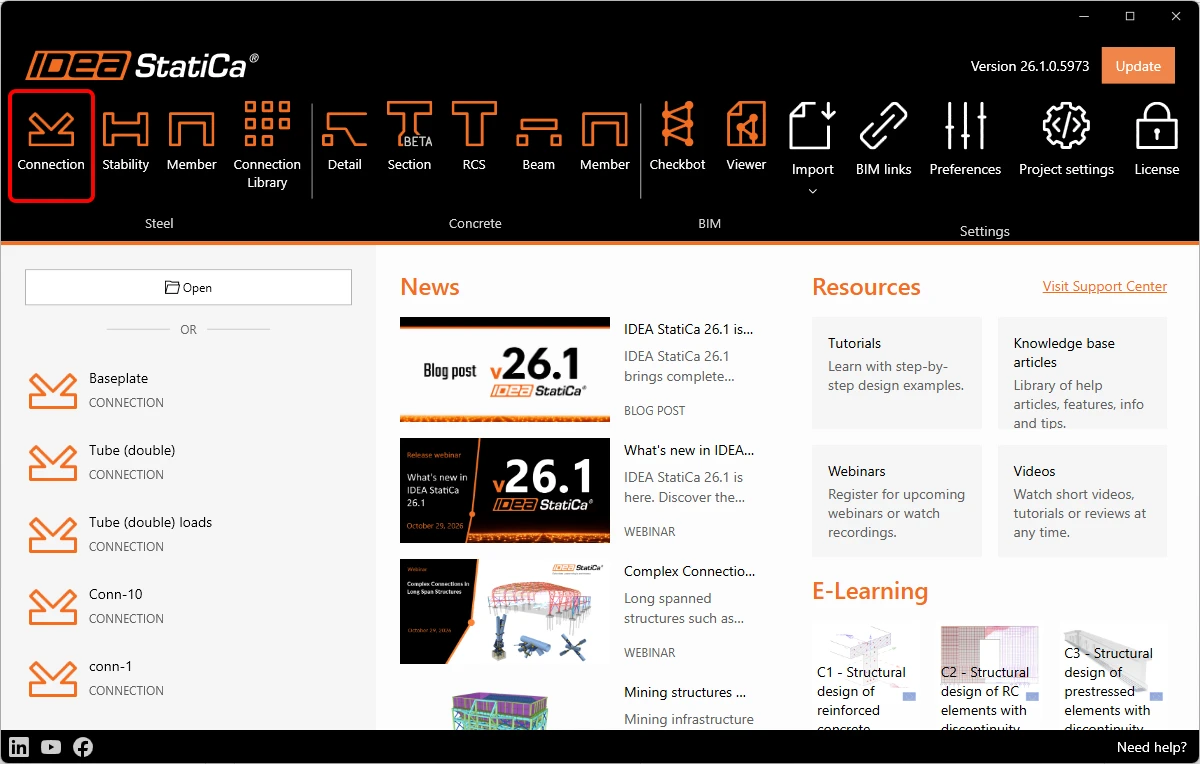
Keep the default settings for anchoring topology and step into the app.

2 Design
Before any adjustments are made, make sure to "Explode" the parametric template. The new Parametric templates offer a fast way of editing simple connections with the change of a few parameters. However, to view the full customization options, explode the parametric template and get access to the manufacturing operations.

Begin by adjusting the column cross-section size of the template connection that just opened. The new cross-section is W12x45.

Alter the Base Plate operation to accomplish the final topology of the loaded concrete block as shown below.
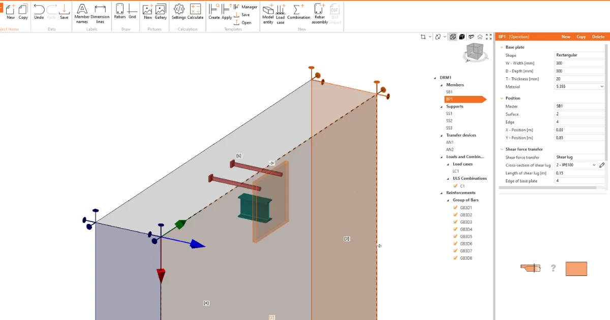
- With Detail 3D, shear can now be transferred through anchors, shear lugs, and friction, too.
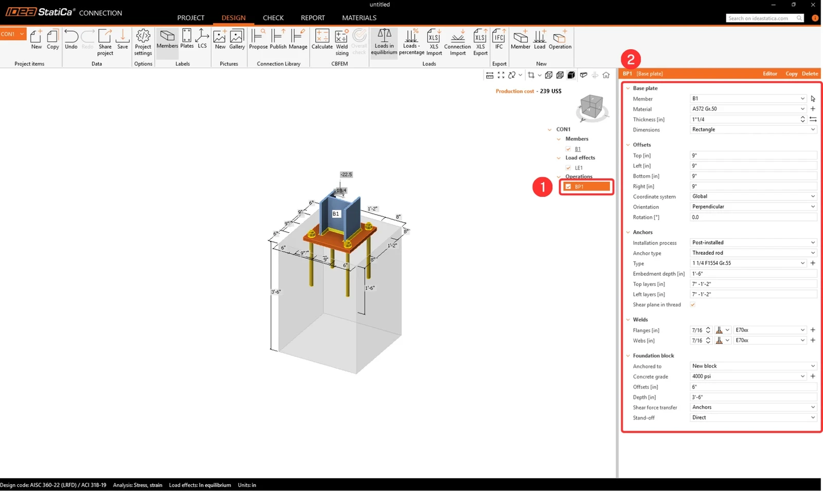
Input the internal forces for the two load cases as shown below. The internal forces cause compression stress on the contact between the ground and the concrete block. By default, the concrete block is assumed to be cracked.
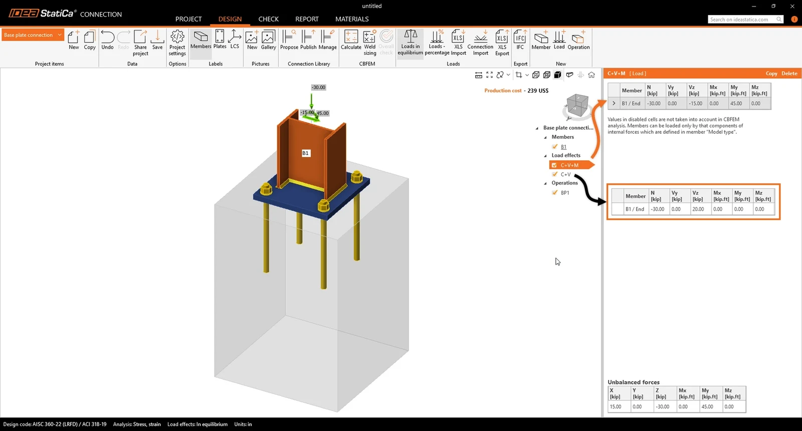
3 Check
Move to the card, check, and calculate. The code check proves the anchors' failure mode. Let's explore this further.
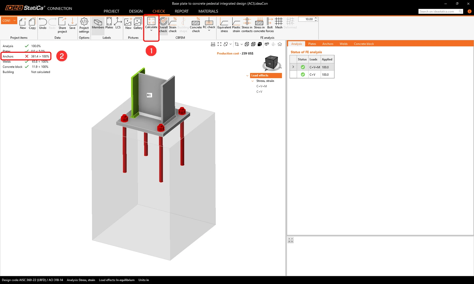
Let's explore the potential failures for tension, shear according to ACI 318 Section 17.4.

Please review the Detailed Check of the Anchors, as it reveals a nonconformity on the first page. This will inform you of the code checks performed and what exactly is failing. It is recommended that you take the necessary actions to address this issue.
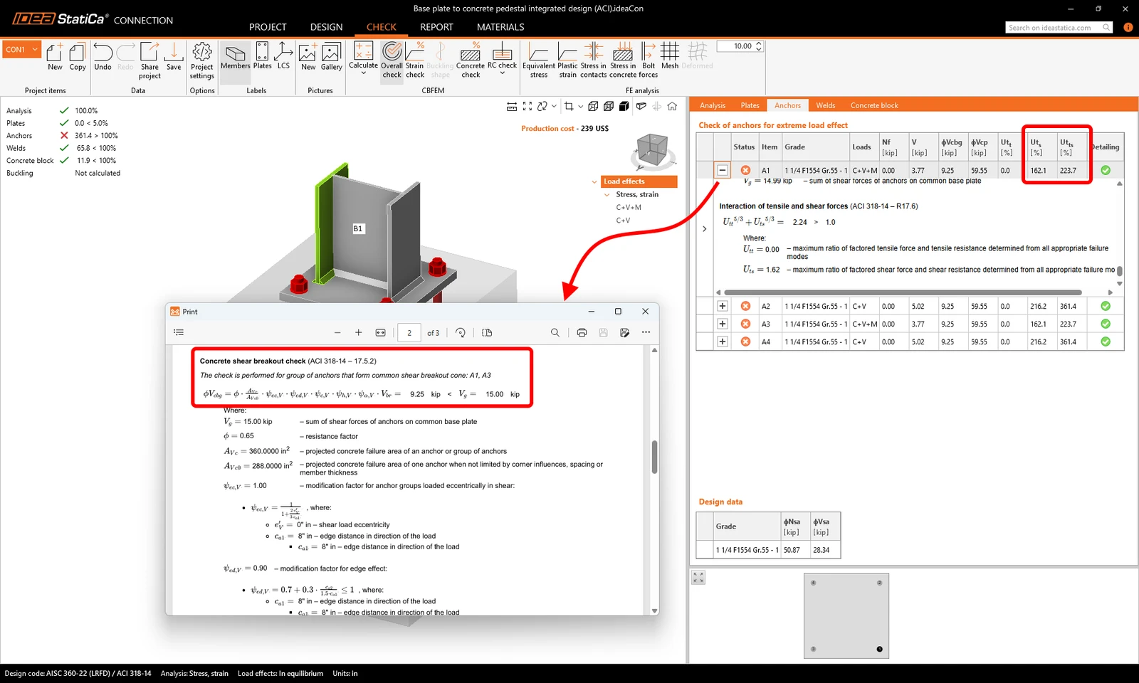
Analyzing the failing Anchor Checks:
- The problem is caused by the Concrete breakout resistance of anchors.
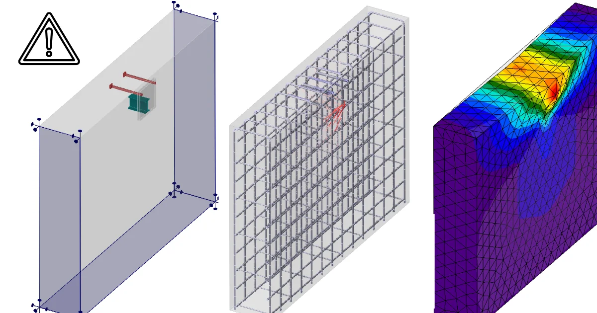
- This issue can be easily solved in IDEA StatiCa Detail, powered by the 3D CSFM method. It helps to overcome the model of plain unreinforced concrete cracked blocks in IDEA StatiCa Connection.
4 Export
The in-house developed application IDEA StatiCa Connection now features a powerful BIM link into Detail, allowing for the design and check of reinforced concrete blocks with multiple combinations.
Prerequisites for export:
- The model has to be pre-calculated, and the results included
Go to the card Check -> RC check -> Save.
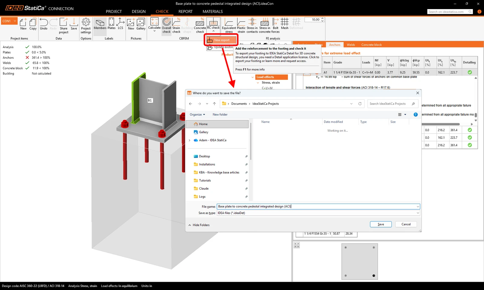
The export is allowed only for the anchoring topology. The export allows the transfer of:
- The concrete block
- Anchors
- The base plate
- Loads
Additional information and parameters that are set according to the corresponding settings in the Connection:
- Shear transfer (through Anchors, Shear lugs, and Friction)
- Material
- Anchorage Type: Post-installed (Adhesive) /Cast-in place
- Anchorage type at the end: Washer/Straight/Bend/Hook/Loop
- Friction coefficient
5 Design
This section will allow you to modify Members, Supports, Loads&Combinations, and Rebar assembly.
After opening the Detail app, close the Reinforcement Library templates with Close.
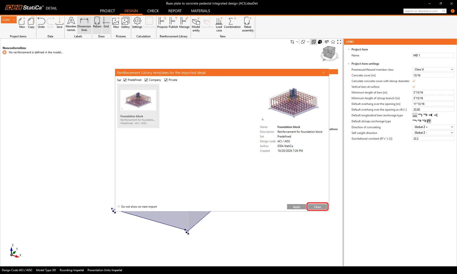
Support
The ground has some stiffness, which should be considered for precise design. The Surface Support enables stiffness in all three directions and is set as the default inactive in tension (boundary nonlinearity).
- Please be cautious while making assumptions about boundary conditions. In the case of nonlinearity, if the moments are quite high, the concrete block's support in tension may turn over during analysis, causing large rotations. This may lead to a divergent model due to the flexible body motion.
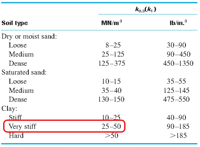
Since our model is a pedestal on which the bars are extended onto the pad foundation, go ahead and deselect the compression-only support option for the Z direction. This will allow continuous reinforcement to interconnect with the foundation.
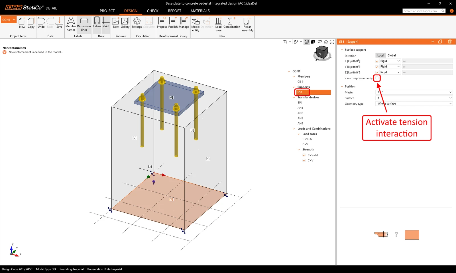
Transfer devices
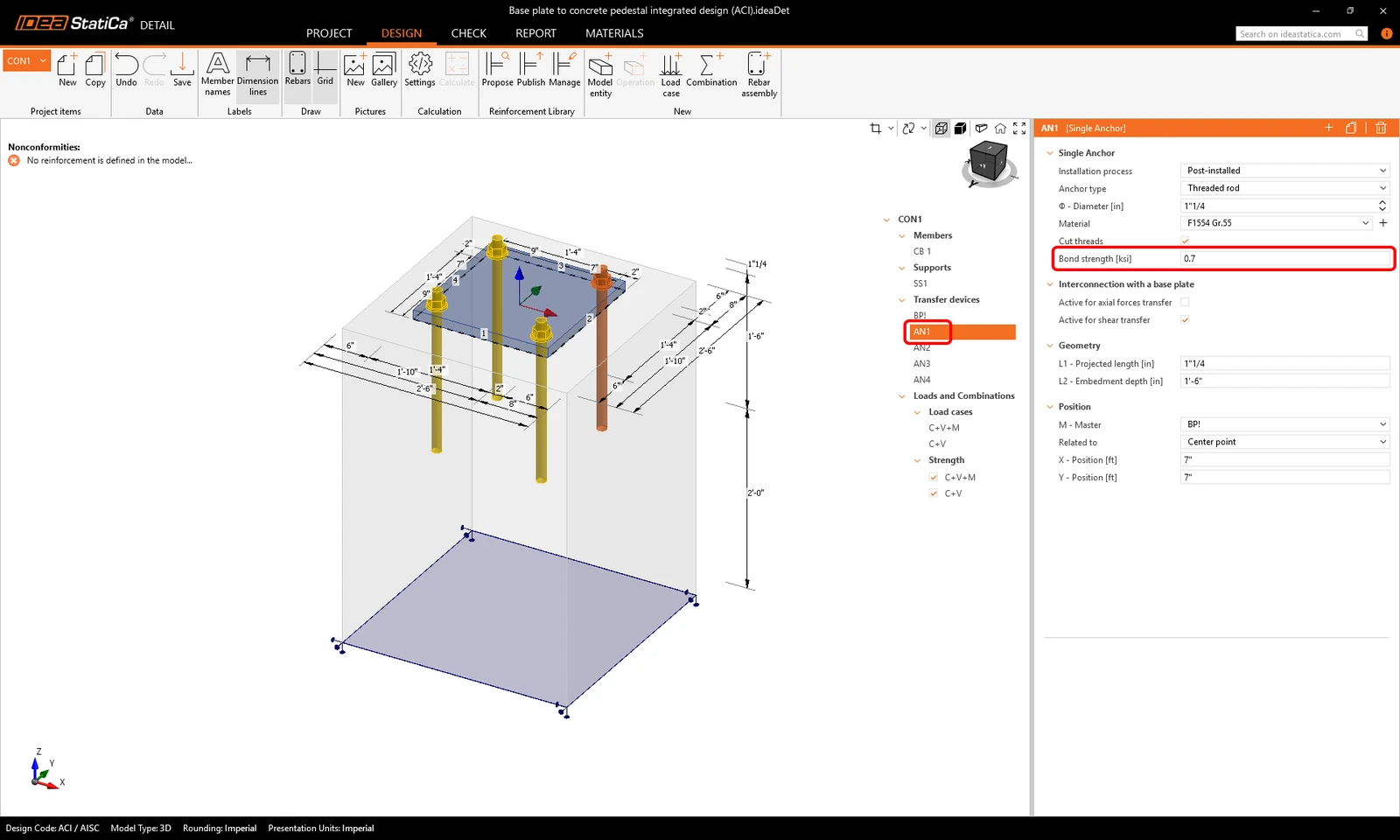
The anchors are taken over from IDEA StatiCa Connection. Two types of anchors can be selected.
Cast-in-place anchors:
- Pre-installed anchors with the same properties in bond as the reinforcement bars
Post-installed (Adhesive) anchors:
- Post-installed (Adhesive/ Chemical anchors) with the option to customize your bond strength based on the actual bond strength.
Steel reinforcement modeling
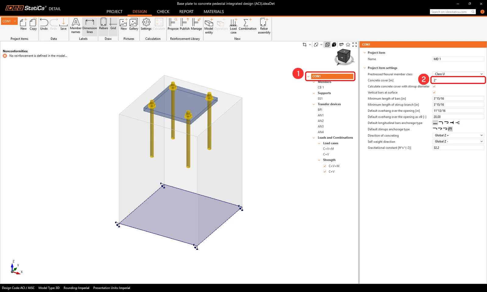
Set the concrete cover to 2 in, which will be used as the default value for the reinforcement.
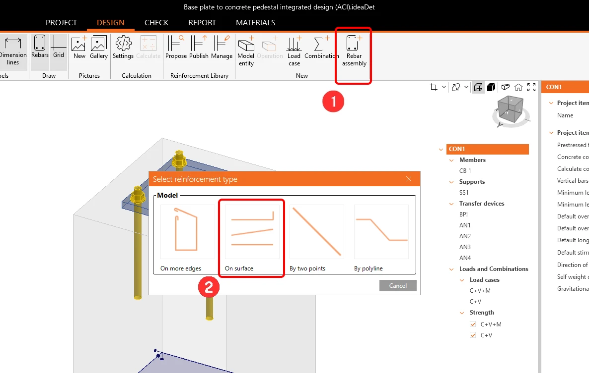
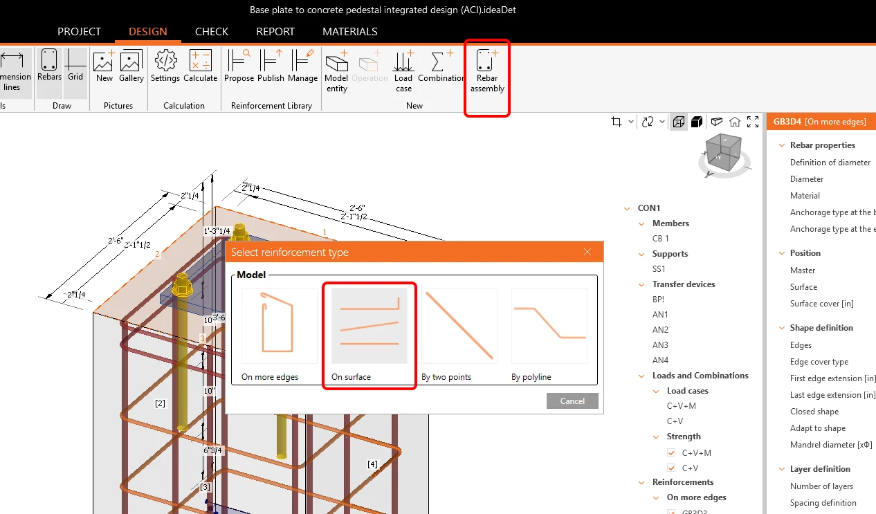
Begin reinforcing the pedestal by adding the bars. Click the Rebar assembly icon and choose a reinforcement type On surface.
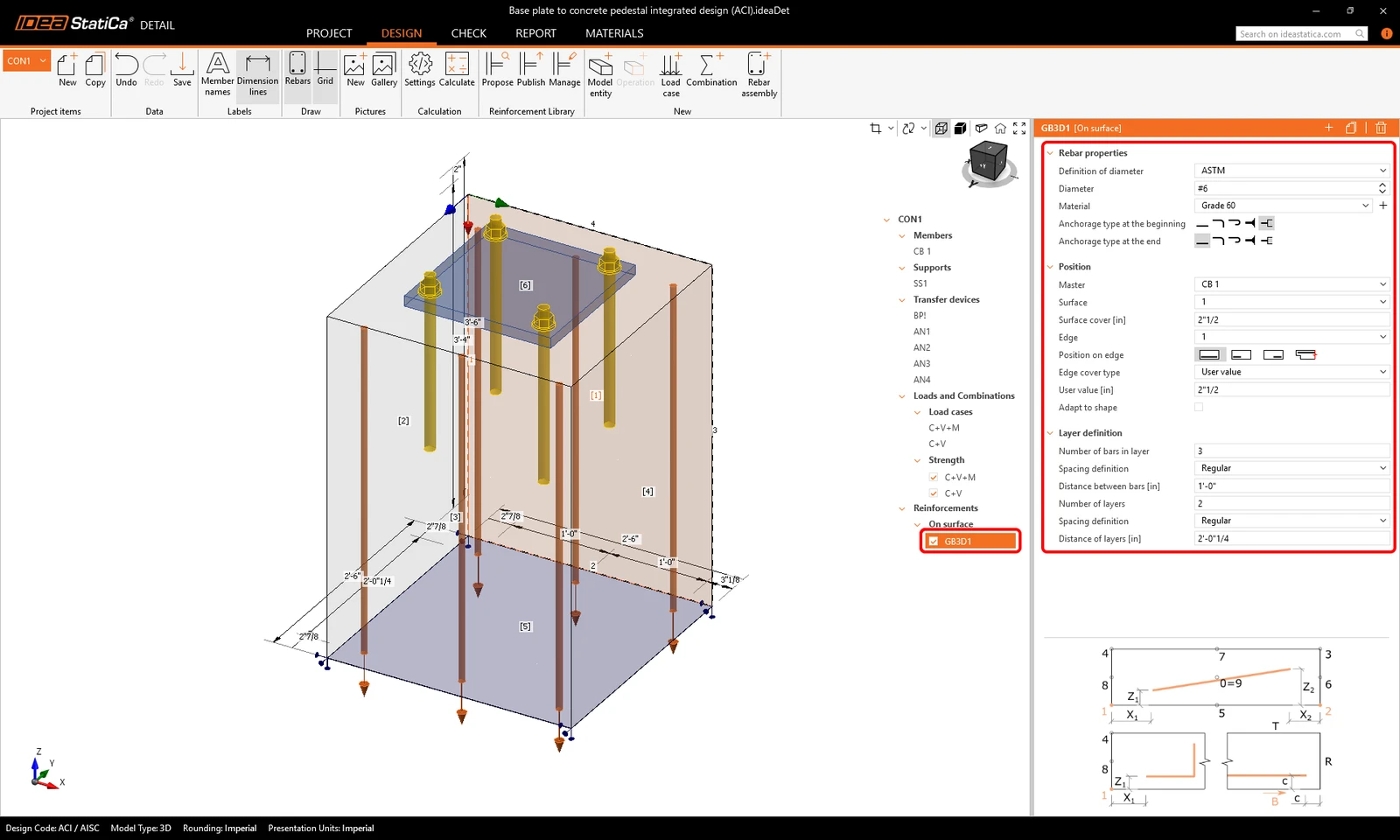
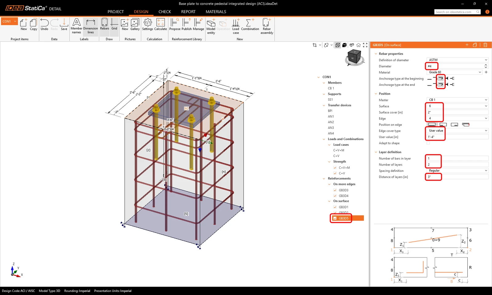
Select the reinforcement item GB3D1 and fill out the parameters.
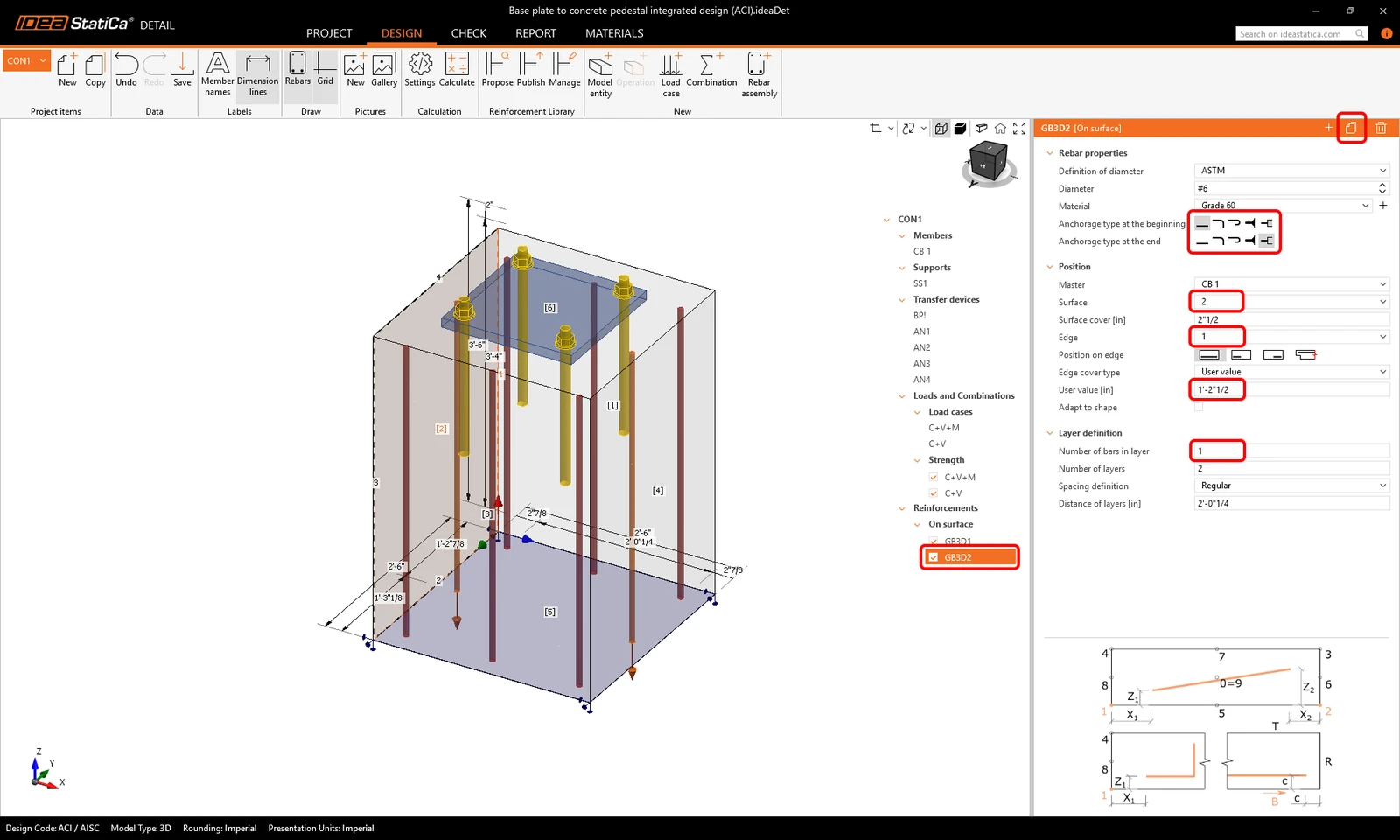
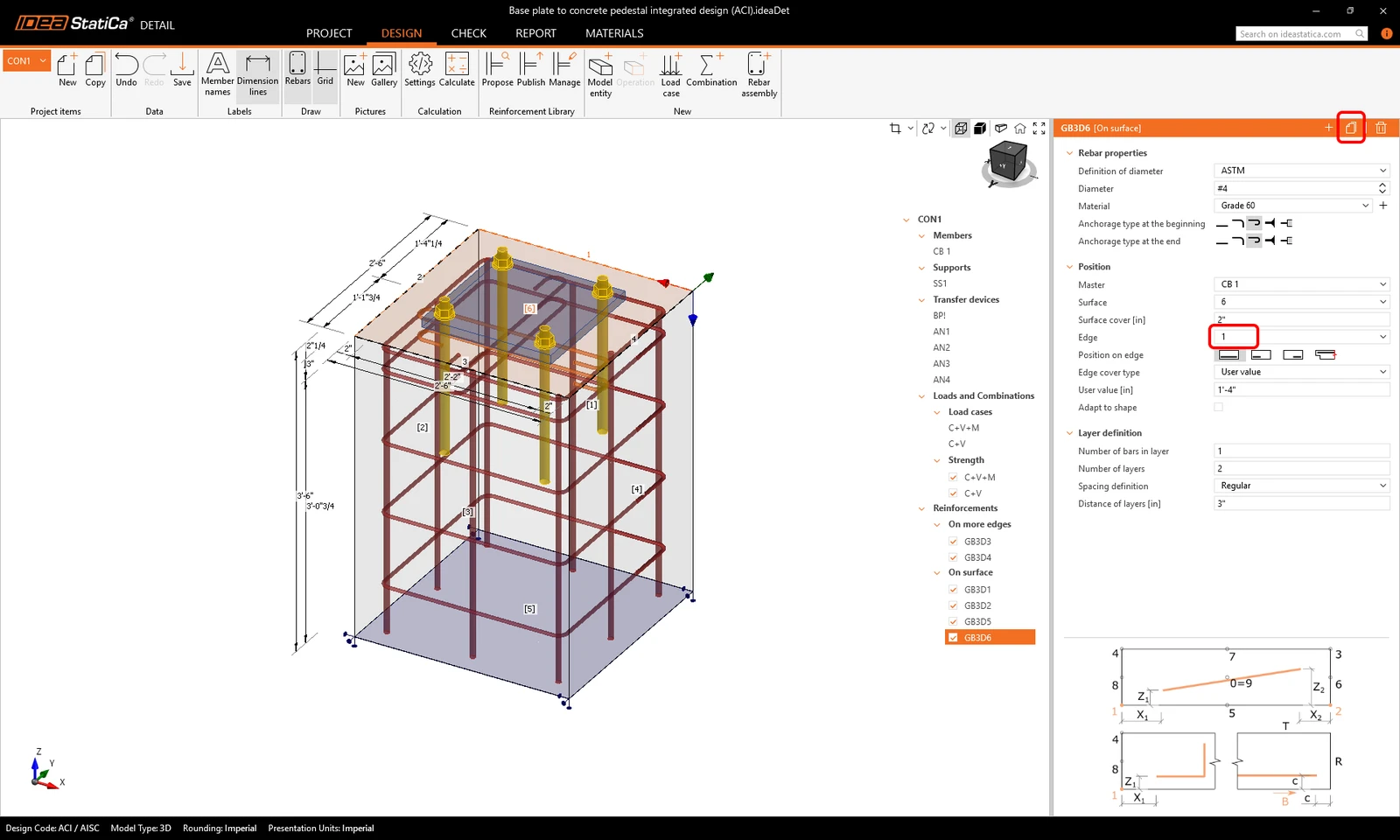
We now need to add the rest of the bars. Copy the operation and change the parameters circled in red as shown below.
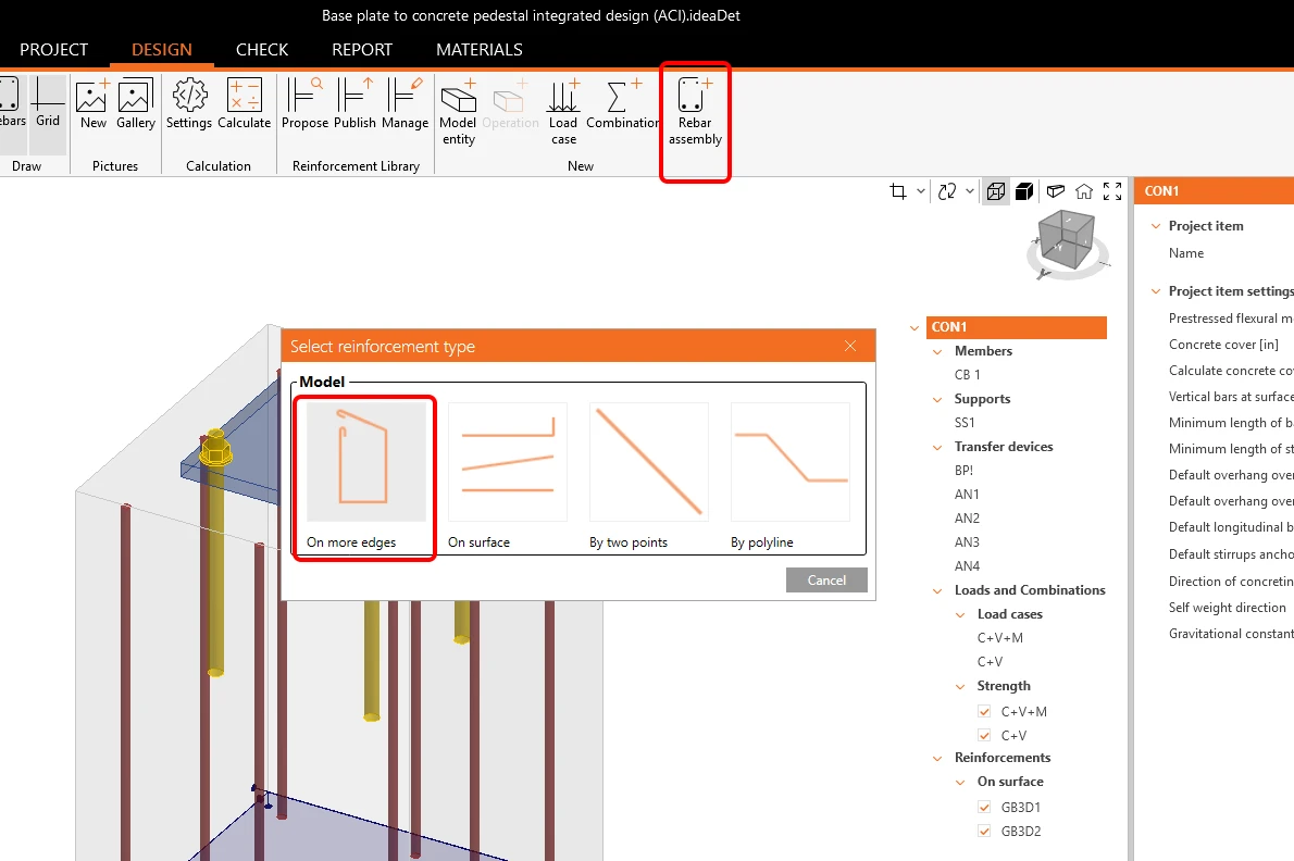
To add the initial ties, add a new group of bars On more edges.
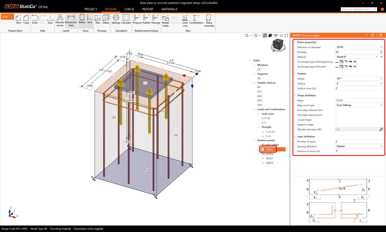
And provide the necessary inputs for the parameters.
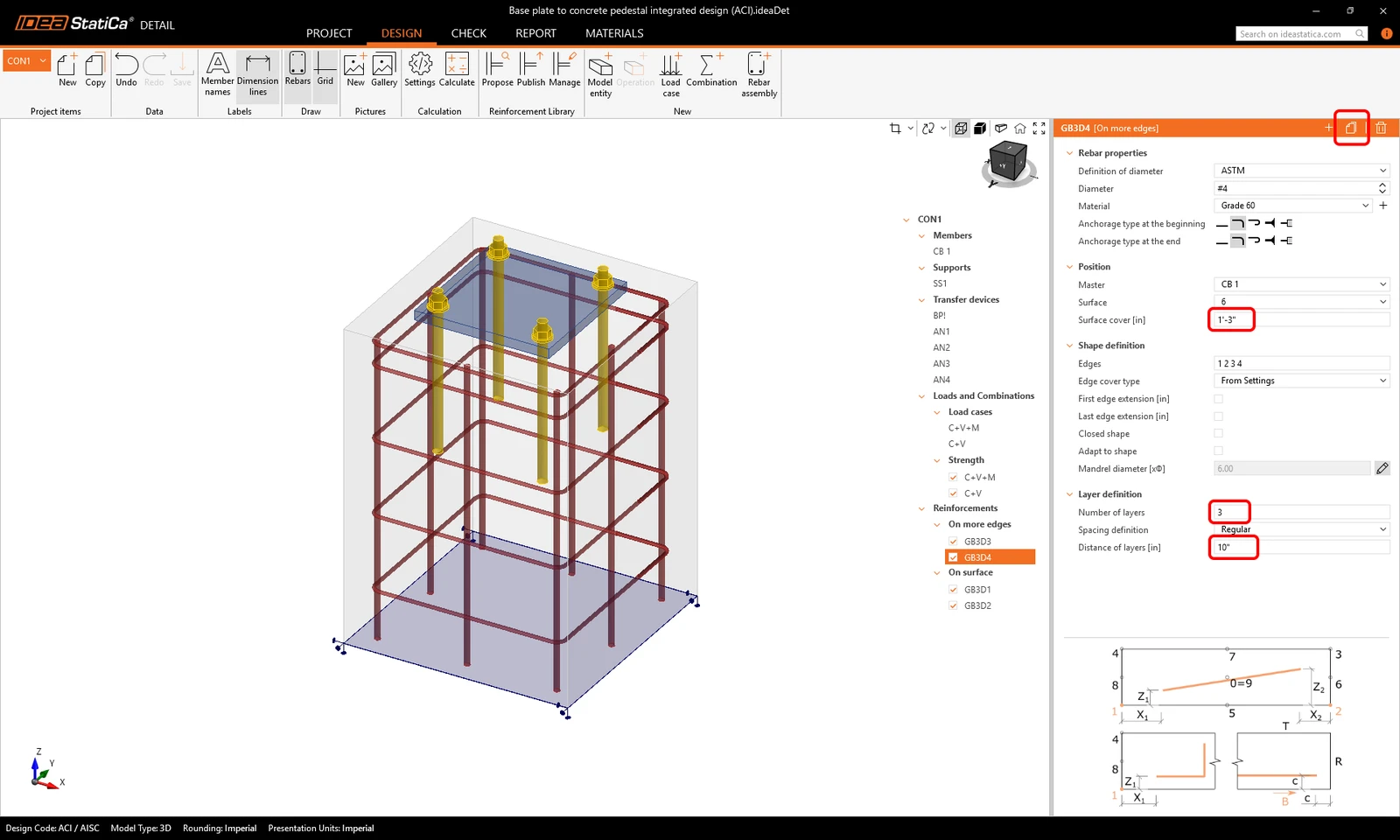
Copy the operation and change the Surface cover, Number of layers, and Distance of layers to add the rest of the hoops to the pedestal.
The last part is to add the shear reinforcement to the pedestal. In this model, we will add shear reinforcement for both directions. Add the rebars On surface.
Adjust the parameters.
And copy the shear reinforcement for the other direction.
Loads and combinations
Combinations are taken over from IDEA StatiCa Connection. To learn more about the import details, please follow the link - Import of anchoring from Connection to Detail.
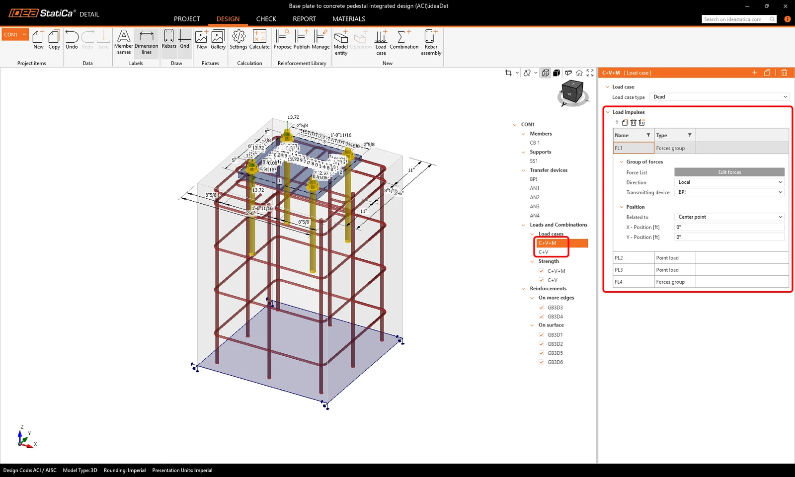
Make a new load case Self-weight. Self-weight is automatically added to all existing load combinations.
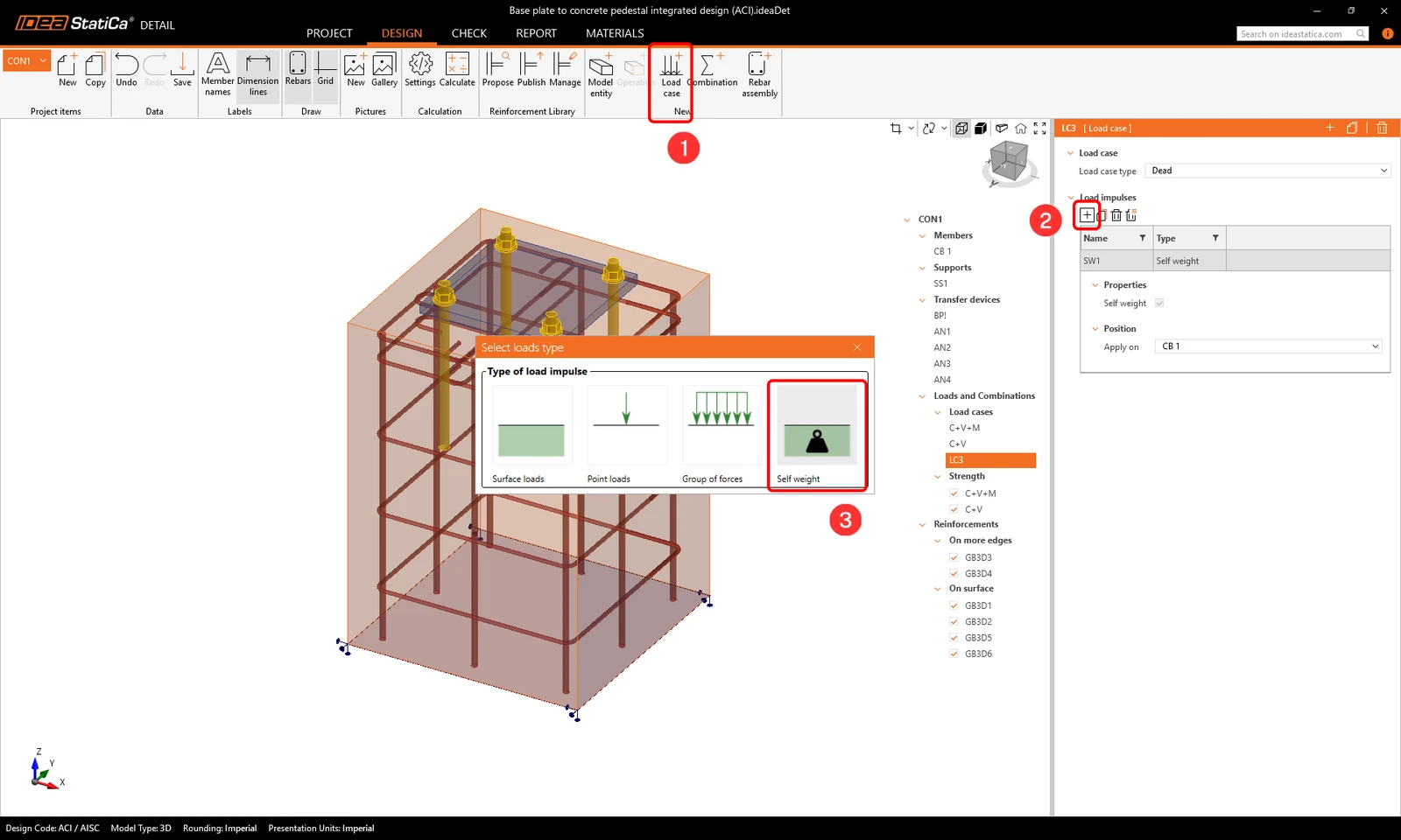
6 Check
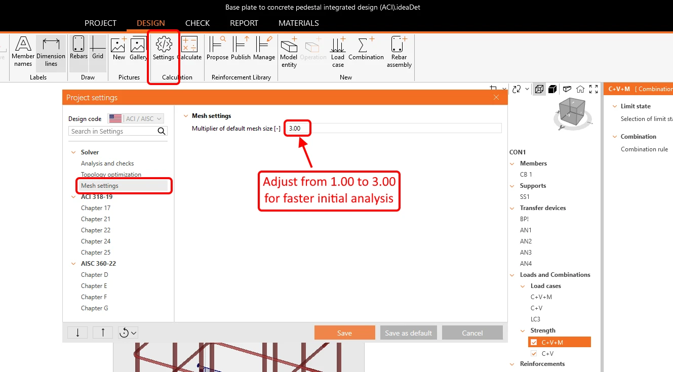
Before running the analysis, we highly recommend changing the mesh multiplier to two or three in order to speed up the calculation. This step is not mandatory, but it can reduce computational time and help detect any divergence issues. If everything works smoothly and no problems arise, you can switch back to a multiplier of one.
Go to Check tab and click Calculate. The Summary results and Stress flow display are shown by default.
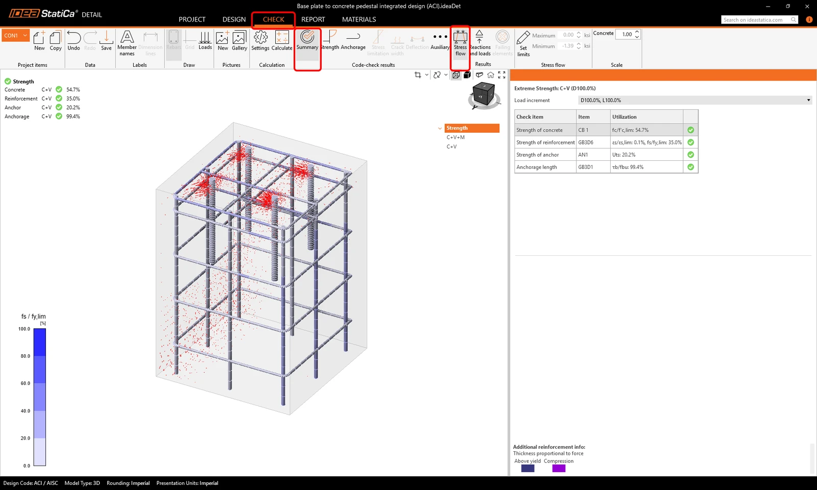
Results
Equivalent Principal Stress
The equivalent principal stress (EPS) in concrete is determined based on the volume behavior of the concrete block. The areas that experience the highest load are identified and highlighted. More information about equivalent principal stress is enclosed in this article of the theoretical background.
Turn on the mesh and select the load combination N+V+M.
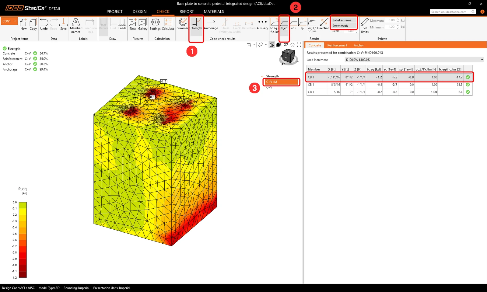
Stress in rebars
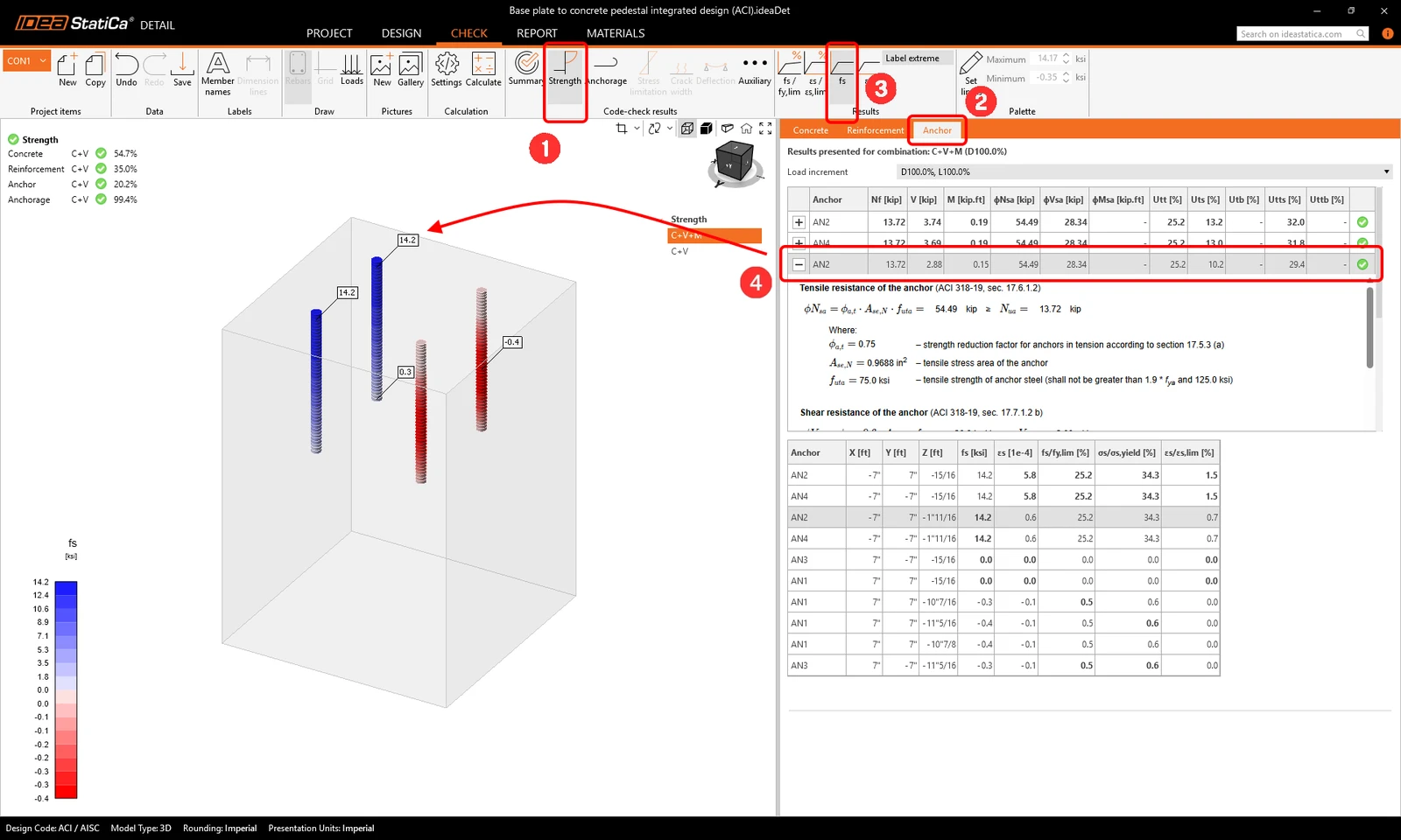
During the Reinforcement and Anchor Check, the stresses can be observed for each reinforcement and forces for each anchor. You can also change the result order to view the most stressed parts of each item. From the re-organized results, it is faster to notice which anchors and reinforcements are being utilized the most.
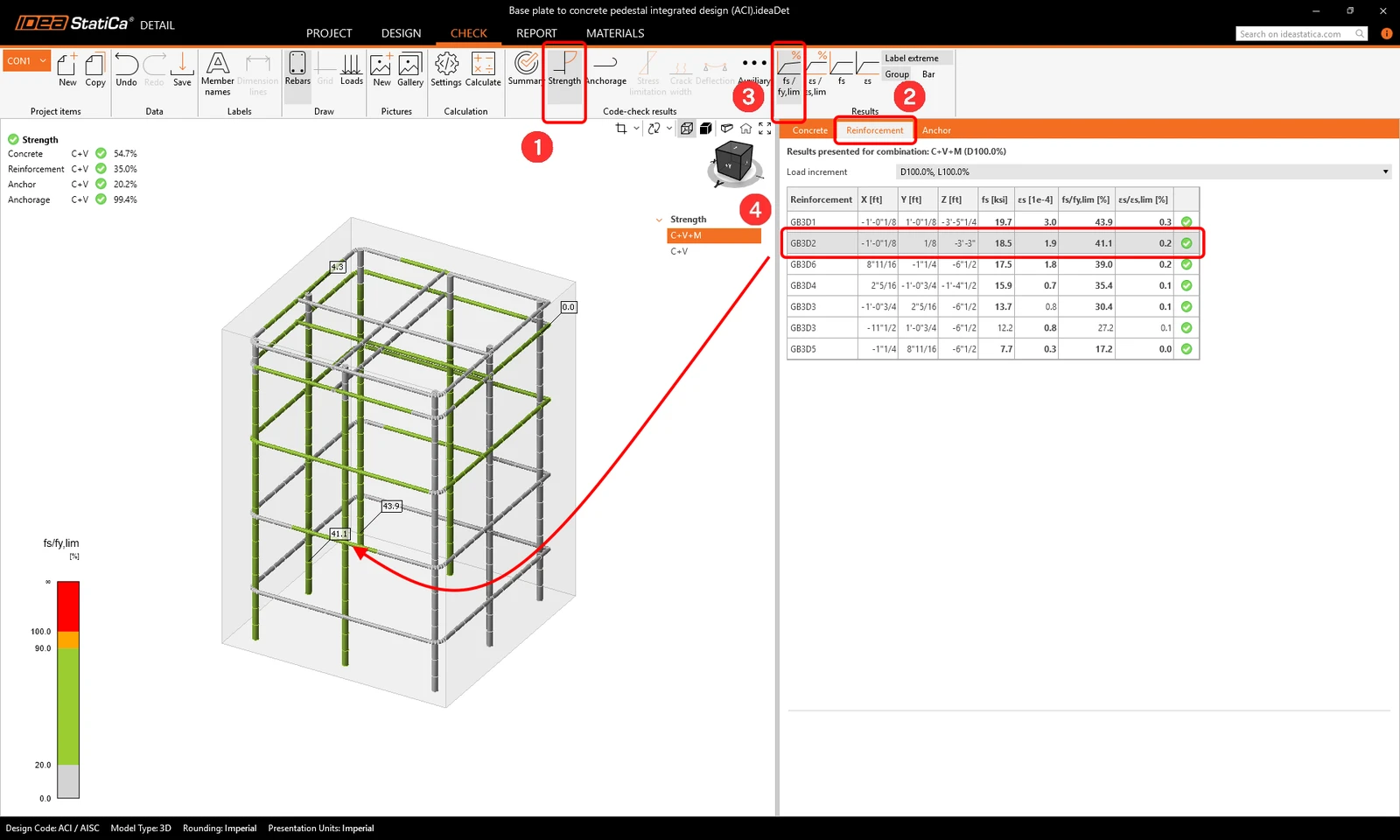
When displaying the utilization of reinforcement, the user can clearly see which reinforcement contributes to transferring the load and preventing the concrete cone failure.
Anchorage
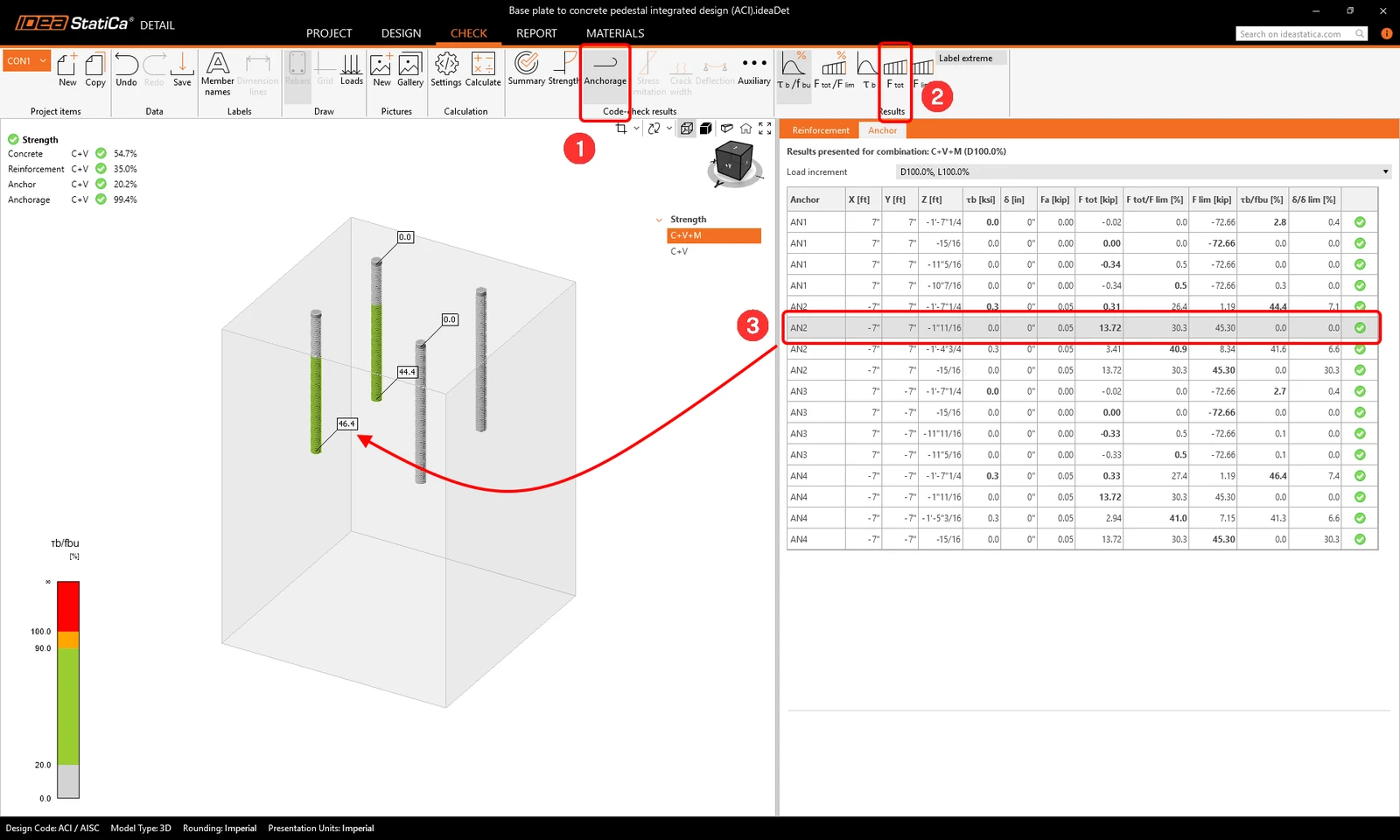
Double-check the Anchorage settings and activate the Total Force in Anchors. The forces in the anchors may vary slightly due to differences in the calculation approaches for the concrete block. The differences are not significant, though.
Deformations
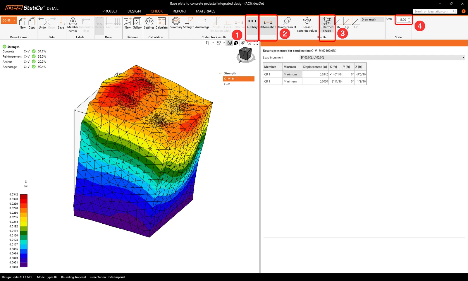
Move to Auxiliary and turn on the Deformation.
It is not necessary to perform a deformation check, but it is highly recommended to check the deformation after analysis to ensure that the model is not experiencing large deformation, large rotation, or any finite element is damaged. This will provide an overview of the analysis results and help identify any issues that may have arisen during the analysis.
7 Report
At last, go to the Report Preview/Print. IDEA StatiCa offers a fully customizable report to print out or save in an editable format.
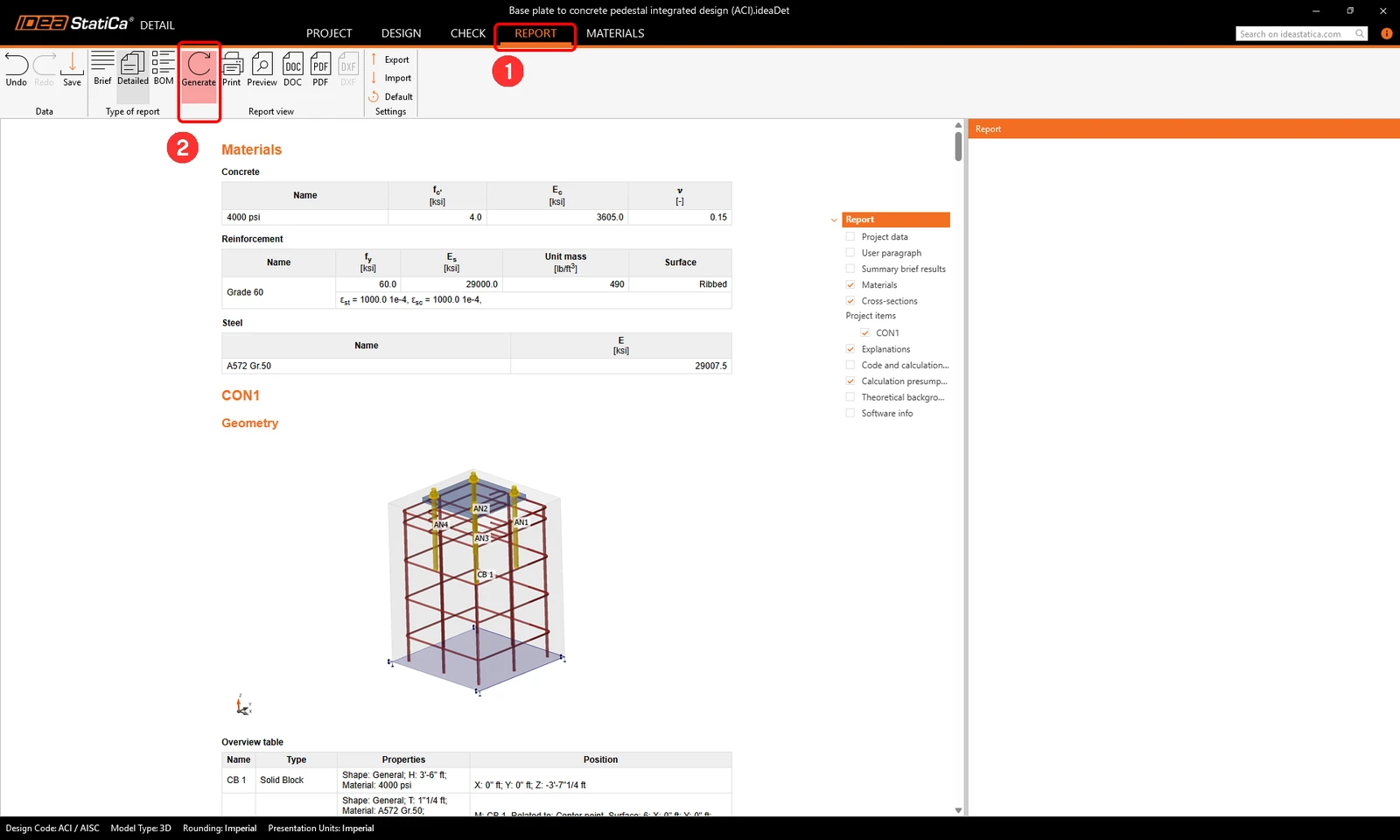
You have checked the whole connection design according to AISC and ACI 318. The steel part was checked in IDEA StatiCa Connection, and the concrete block was code-checked in IDEA StatiCa Connection and Detail.