Idea Statica
  • Steel
  • Concrete
  • Support & Learning
  • Pricing
  • Company
  • Steel overview
  • Connection design
  • Member design
  • Parametric design
  • Steel case studies
  • Concrete overview
  • Walls and D-regions
  • Anchoring design
  • Concrete case studies
  • BIM Overview
  • Supported integrations
  • Checkbot
  • Viewer
  • APIs
  • Support Center
  • E-learning & certification
  • Blog
  • Downloads & Licensing
  • Plans
  • Free community tool
  • Enterprise customers
  • Students & educators
  • How much will you save?
  • About us
  • Contact
  • Research & development
  • Authorized resellers
  • Meet our customers
  • Career
  • Steel
    Steel overviewConnection designMember designParametric designSteel case studies
  • Concrete
    Concrete overviewWalls and D-regionsAnchoring designConcrete case studies
  • BIM OverviewSupported integrationsCheckbotViewerAPIs
  • Support & Learning
    Support CenterE-learning & certificationBlogDownloads & Licensing
  • Pricing
    PlansFree community toolEnterprise customersStudents & educatorsHow much will you save?
  • Company
    About usContactResearch & developmentAuthorized resellersMeet our customersCareer
14-Day Trial
14-Day Trial

Subscribe to our newsletter

Company

  • About us
  • Partners
  • Careers
  • Patent

Resources

  • Customer projects
  • Case studies
  • Connection Library
  • Verification books

Legal

  • EULA
  • Privacy policy
  • California Privacy
  • TOS Viewer
  • Licensing

Help

  • Contact
  • Quote request
  • Resellers
  • Downloads
FacebookInstagramLinkedInYouTube

Ā© IDEA StatiCa 2009-2026

Trusted and used worldwide by engineers, fabricators & consultants.

Support CenterKnowledge Base ArticlesTorsion
ConcreteKnowledge baseRCSBeam

Torsion

This article is also available in
ENCZDEESFRITPTNLHUROKRPLTHTRVIZH

Calculation assumptions

The behavior ofĀ a reinforced concreteĀ section subjectedĀ to torsionĀ can be dividedĀ intoĀ twoĀ categoriesĀ -Ā beforeĀ andĀ after the time when the cracks may first be expected to occur. Before aĀ crackĀ theĀ cross-sectionĀ behavesĀ as an elastic material.Ā Torsion stress can be expressed by formula Ā Ā 

Ā Ļ„=Ā TEdWt\tau =~\frac{{{T}_{Ed}}}{{{W}_{t}}}Ļ„=Ā Wt​TEd​​ 

where Wt je sectional module in torsion.

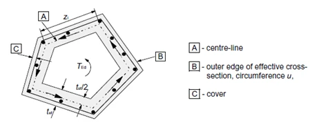
Cracks in the unreinforced member due to principal tensile torsion stress are also ultimate limit state. The behavior of a reinforced concreteĀ section subjectedĀ to torsion can be described on the basis of a thin-walled closed section, see Fig. below.Ā 

EquivalentĀ thin-walledĀ cross-section.\textsf{\textit{\footnotesize{\qquad Equivalent thin-walled cross-section.}}}EquivalentĀ thin-walledĀ cross-section.

Calculation procedure

The process ofĀ a reinforced concreteĀ checkĀ for torsionĀ is veryĀ similar to theĀ check for shear.Ā First of all,Ā we check the concrete resistance.Ā If theĀ concreteĀ check is satisfied, theĀ reinforcementĀ can beĀ designed using the detailingĀ rules.Ā Otherwise,Ā we needĀ to verify the reinforcementĀ and compressive diagonal resistance by calculation.
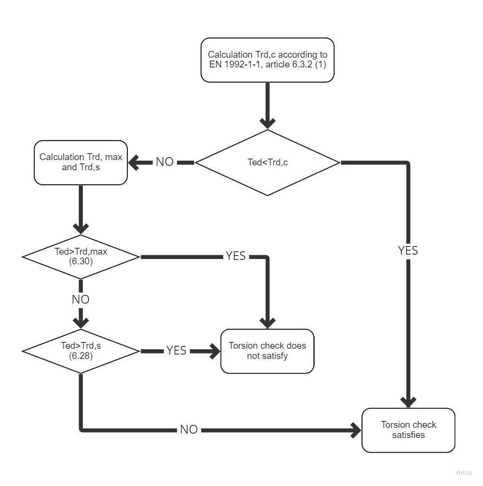
ProcessĀ diagramĀ forĀ torsionĀ check.\textsf{\textit{\footnotesize{\qquad Process diagram for torsion check.}}}ProcessĀ diagramĀ forĀ torsionĀ check.

Resistance

Shear flow in a wall of a thin-walled cross-section under torsion can be expressed as:

Ļ„ttef=Ā TEd2Ak{{\tau }_{t}}{{t}_{ef}}=~\frac{{{T}_{Ed}}}{2{{A}_{k}}}Ļ„t​tef​=Ā 2Ak​TEd​​

Shear force in a wall of a thin-walled cross-section can be expressed as:

V=Ļ„ttefzV={{\tau }_{t}}{{t}_{ef}}zV=Ļ„t​tef​z

WhereĀ 

τ          Shear flow in wall,

tef Ā Ā Ā Ā Ā Ā Ā  is the effective wall thickness,

z Ā Ā Ā Ā Ā Ā Ā Ā Ā  is the side length of wall,

TEdĀ Ā Ā Ā Ā Ā  is the torsion moment,

Ak Ā Ā Ā Ā Ā Ā  is the area enclosed by the center-lines of the connecting walls, including inner hollow areas.

Torsion cracking moment, which may be determined by setting fctd to previous expression. ThusĀ we getĀ expression for theĀ resistance in torsion without torsion reinforcement.

TRd,c=2Akteffctd{{T}_{Rd,c}}=2{{A}_{k}}{{t}_{ef}}{{f}_{ctd}}TRd,c​=2Ak​tef​fctd​

whereĀ  fctd Ā Ā Ā Ā Ā  design axial tensile strength of concrete
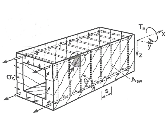
PrinciplesĀ ofĀ TrussĀ analogyĀ forĀ memberĀ underĀ torsionĀ moment.\textsf{\textit{\footnotesize{\qquad Principles of Truss analogy for member under torsion moment.}}}PrinciplesĀ ofĀ TrussĀ analogyĀ forĀ memberĀ underĀ torsionĀ moment.

The member resistance with torsion reinforcement is composed from the resistance of compressive concrete diagonals which is based again on the truss analogy method. Compressive stress in the diagonal can be expressed with help of shear force in the wall of a thin-walled cross-section on the wall surface which is in consideration, i.e.

σc=TEdz2Aksin⁔θzĀ tefcos⁔θ=TEd2Aktefsin⁔θcos⁔θ{{\sigma }_{c}}=\frac{\frac{{{T}_{Ed}}z}{2{{A}_{k}}\sin \theta }}{z~{{t}_{ef}}\cos \theta }=\frac{{{T}_{Ed}}}{2{{A}_{k}}{{t}_{ef}}\sin \theta \cos \theta }σc​=zĀ tef​cosĪø2Ak​sinĪøTEd​z​​=2Ak​tef​sinĪøcosĪøTEd​​

Substitution of  σc=σcwfcd and TEd=TRd,max and expressing of TRd,max we get an equation for the compressive diagonal resistance

TRd,max=2 ν αcwĀ fcdĀ AkĀ tefĀ sin⁔θ cos⁔θ{{T}_{Rd,max}}=2~\nu ~{{\alpha }_{cw}}~{{f}_{cd}}~{{A}_{k}}~{{t}_{ef~\sin \theta ~\cos \theta }}TRd,max​=2 ν αcw​ fcd​ Ak​ tefĀ sinĪøĀ cosθ​

whereĀ Ā 

ν Ā Ā Ā Ā Ā Ā Ā Ā  = 0,6 pro fck ≤ 60MPa or Ā for fck > 60MPa

αcw       coefficient which takes account the state of compressive stress in compression chord

fcd Ā Ā Ā Ā Ā Ā  design value of concrete compressive strength

the shear reinforcement resistance subjected to torsion is again based on stress in the compression diagonal. The stirrup force is equal to the stress in the compressed diagonal on the area which corresponds to the particular stirrup line, i.e.

Aswfywd=TEd2Aktefsin⁔θcos⁔θ tefĀ ssin⁔2Īø=TEdĀ s2Akcot⁔θ {{A}_{sw}}{{f}_{ywd}}=\frac{{{T}_{Ed}}}{2{{A}_{k}}{{t}_{ef}}\sin \theta \cos \theta }~{{t}_{ef}}~s{{\sin }^{2}}\theta =\frac{{{T}_{Ed}}~s}{2{{A}_{k}}\cot \theta }~Asw​fywd​=2Ak​tef​sinĪøcosĪøTEd​​ tef​ ssin2Īø=2Ak​cotĪøTEd​ s​ 

Substituting Ā TEd=TRd,s and expressing TRd,s Ā we get equation:

Ā TRd,s=2AkAswfywdsĀ cot⁔θ{{T}_{Rd,s}}=2{{A}_{k}}\frac{{{A}_{sw}}{{f}_{ywd}}}{s}~\cot \thetaTRd,s​=2Ak​sAsw​fywd​​ cotĪøĀ 

If the longitudinal and shear reinforcement quantity is known, we can define angle Īø by the expression

tan⁔2Īø=AswfywdsAslfyduk{{\tan }^{2}}\theta =\frac{\frac{{{A}_{sw}}{{f}_{ywd}}}{s}}{\frac{{{A}_{sl}}{{f}_{yd}}}{{{u}_{k}}}}tan2Īø=uk​Asl​fyd​​sAsw​fywd​​​ 

Substitution for TRd,sĀ we get

TRd,s=2AkAswsfywdĀ AslukĀ fyd{{T}_{Rd,s}}=2{{A}_{k}}\sqrt{\frac{{{A}_{sw}}}{s}{{f}_{ywd~}}\frac{{{A}_{sl}}}{{{u}_{k}}}~{{f}_{yd}}}TRd,s​=2Ak​sAsw​​fywd ​uk​Asl​​ fyd​​  

Where

AswĀ Ā Ā Ā Ā  shear reinforcement area

s Ā Ā Ā Ā Ā Ā Ā Ā Ā  is the radial spacing of stirrups of shear reinforcement

fywd Ā Ā Ā Ā  is the effective design strength of the shear reinforcement

AslĀ Ā Ā Ā Ā Ā  longitudinal reinforcement area

uk Ā Ā Ā Ā Ā Ā Ā  is the outer circumference of the cross-section

fywd Ā Ā Ā Ā  is the effective design strength of the longitudinal reinforcement

The force in the longitudinal reinforcement can be deducted from The shear force in a wall of a section subject to a pure torsional moment, which is give as:

V=TEd2AkukV=\frac{{{T}_{Ed}}}{2{{A}_{k}}}{{u}_{k}}V=2Ak​TEd​​uk​

That force is transformed to longitudinal direction and we get:

Fl=TEduk2AkĀ tan⁔θ{{F}_{l}}=\frac{{{T}_{Ed}}{{u}_{k}}}{2{{A}_{k}}~\tan \theta }Fl​=2Ak​ tanĪøTEd​uk​​

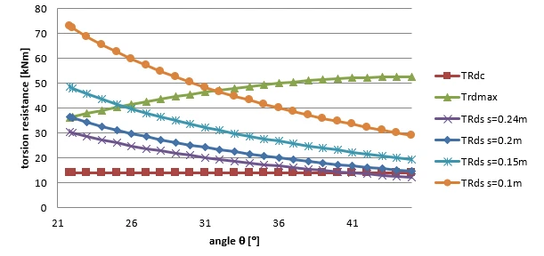
The permitted range of the values for angle Īø is similar to the shear check, i.e 1 < cot Īø < 2,5. Dependency between resistances can be seen in Fig. below. The diagram showsĀ that withĀ increasingĀ the angleĀ Īø Ā the resistance TRd,max isĀ growing, Ā the resistance TRd.s is decreasingĀ and resistance TRd,cĀ isĀ constant,Ā since it isĀ not basedĀ onĀ the truss analogy method.

ZaˊvislostĀ uˊnosnostiĀ pru˚rˇezuĀ vĀ kroucenıˊ naĀ uˊhluĀ Īø.\textsf{\textit{\footnotesize{\qquad ZĆ”vislost Ćŗnosnosti prÅÆÅ™ezu v kroucenĆ­ na Ćŗhlu Īø.}}}ZaˊvislostĀ uˊnosnostiĀ pru˚rˇezuĀ vĀ kroucenıˊ naĀ uˊhluĀ Īø.

Calculation of cross-section characteristics for torsion

To check theĀ cross-sectionĀ for torsion it isĀ necessaryĀ to establishĀ a so-calledĀ equivalent thin-walled closed section.Ā InĀ determining the dimensionsĀ of the equivalentĀ thin-walled cross-section by assumingĀ a rectangular shape.Ā For theĀ trueĀ areaĀ of rectangularĀ states AĀ =Ā bƗh and for theĀ circumferenceĀ ofĀ rectangle u =2Ā (bĀ +h).Ā UsingĀ theseĀ twoĀ equationsĀ canĀ provideĀ alternativeĀ thinĀ rectangle-shaped areaĀ andĀ peripheryĀ ofĀ the originalĀ cross-section.Ā Solving twoĀ equationsĀ with twoĀ unknownsĀ we get:

b=āˆ’u±u2āˆ’16Aāˆ’4  ⁣ ⁣  ⁣ ⁣ b=\frac{-u\pm \sqrt{{{u}^{2}}-16A}}{-4}\text{ }\!\!~\!\!\text{ }b=āˆ’4āˆ’u±u2āˆ’16A​​   

h=(uāˆ’2b)2h=\frac{\left( u-2\text{b} \right)}{2}h=2(uāˆ’2b)​

The wall thickness of the effective cross-section can be define from peripheryĀ and section area as:

t=A/ut=\text{A}/\text{u}t=A/u

Then the area and peripheryĀ defined by center line of the effective cross-section:

Ak=(hāˆ’t)  ⁣ ⁣  ⁣ ⁣ (bāˆ’t)  ⁣ ⁣  ⁣ ⁣ {{A}_{k}}=\left( \text{h}-\text{t} \right)\text{ }\!\!~\!\!\text{ }\left( \text{b}-\text{t} \right)\text{ }\!\!~\!\!\text{ }Ak​=(hāˆ’t)Ā Ā Ā (bāˆ’t)Ā Ā Ā 

uk=2((hāˆ’t)+  ⁣ ⁣  ⁣ ⁣ (bāˆ’t)){{u}_{k}}=2\left( \left( \text{h}-\text{t} \right)+\text{ }\!\!~\!\!\text{ }\left( \text{b}-\text{t} \right) \right)uk​=2((hāˆ’t)+Ā Ā Ā (bāˆ’t))

The problem with thisĀ method isĀ forĀ cross-sectionĀ of typeĀ TĀ withĀ a wideĀ plate when the overall area and peripheryĀ is takenĀ toĀ calculate theĀ dimensions (includingĀ thisĀ plate).Ā In the future versions of IDEA RCSĀ program, the selection of the most massive cross-section part will be enabled,Ā whichĀ willĀ be usedĀ to check theĀ torsion.