Idea Statica
  • Steel
  • Concrete
  • BIM & Workflows
  • Support & Learning
  • Pricing
  • Company
  • Steel overview
  • Connection design
  • Member design
  • Parametric design
  • Steel case studies
  • Concrete overview
  • Walls and D-regions
  • Anchoring design
  • Concrete case studies
  • BIM Overview
  • Supported integrations
  • Checkbot
  • Viewer
  • APIs
  • Support Center
  • E-learning & certification
  • Blog
  • Downloads & Licensing
  • Plans
  • Free community tool
  • Enterprise customers
  • Students & educators
  • How much will you save?
  • About us
  • Contact
  • Research & development
  • Authorized resellers
  • Meet our customers
  • Career
  • Steel
    Steel overviewConnection designMember designParametric designSteel case studies
  • Concrete
    Concrete overviewWalls and D-regionsAnchoring designConcrete case studies
  • BIM & Workflows
    BIM OverviewSupported integrationsCheckbotViewerAPIs
  • Support & Learning
    Support CenterE-learning & certificationBlogDownloads & Licensing
  • Pricing
    PlansFree community toolEnterprise customersStudents & educatorsHow much will you save?
  • Company
    About usContactResearch & developmentAuthorized resellersMeet our customersCareer
14-Day Trial
14-Day Trial
  • Steel
  • Concrete
  • BIM & Workflows
  • Support & Learning
  • Pricing
  • Company

Subscribe to our newsletter

Company

  • About us
  • Partners
  • Careers
  • Patent

Resources

  • Customer projects
  • Case studies
  • Connection Library
  • Verification books

Legal

  • EULA
  • Privacy policy
  • California Privacy
  • TOS Viewer
  • Licensing

Help

  • Contact
  • Quote request
  • Resellers
  • Downloads
FacebookInstagramLinkedInYouTube

© IDEA StatiCa 2009-2026

Trusted and used worldwide by engineers, fabricators & consultants.

Support CenterKnowledge Base ArticlesHow to import a plate from DXF
How to import a plate from DXF
Using the plate Editor to shape a plate
How to design a haunch
Mesh generation error for a plate imported from DXF
Packing plate to merge different sizes of members
Plate and weld clash check
How to import a plate from DXF
SteelConnection designKnowledge baseConnectionGeometry

How to import a plate from DXF

This article is also available in
ENCZDEESFRITPTNLHUROKRPLTHTRVIZH

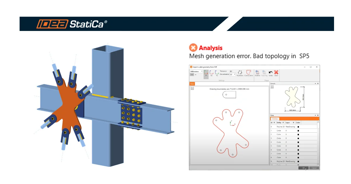
In the case of plates with a general shape, instead of editing edges using Editor in the operation Stiffening plate, you can consider importing them from DXF.

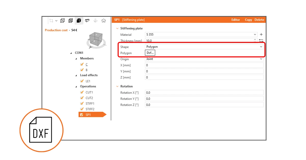
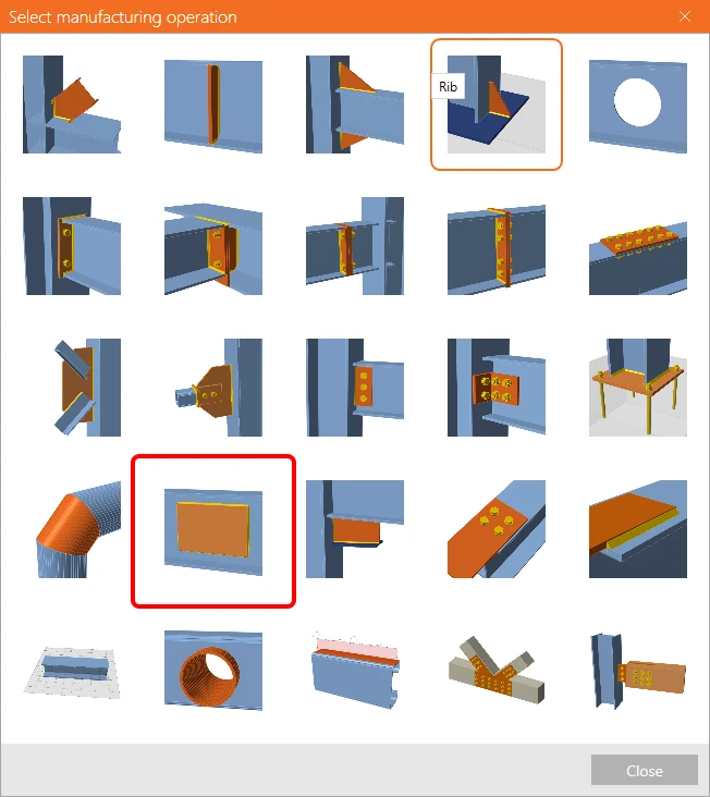
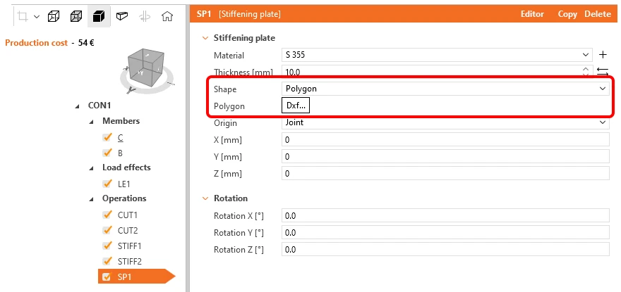
Add a new operation, Stiffening plate, and for the parameter Shape, select the option Polygon. Click the DXF... button... and choose your DXF file containing the plate outline shape.

Please note that the plate outline shape in the DXF file must be exploded to the simple entities (line, arch), and other applications do not have the DFX file open.
Plate
DXF

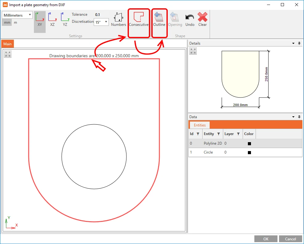
Then, click the edge of the shape to pick a line in the selection. You can manually pick the other edge lines by pressing the Ctrl button or clicking the command Consecutive in the top ribbon. You must select a closed shape. Then click the command Outline.
DXF

The shape of the imported plate is drawn in the Details window.

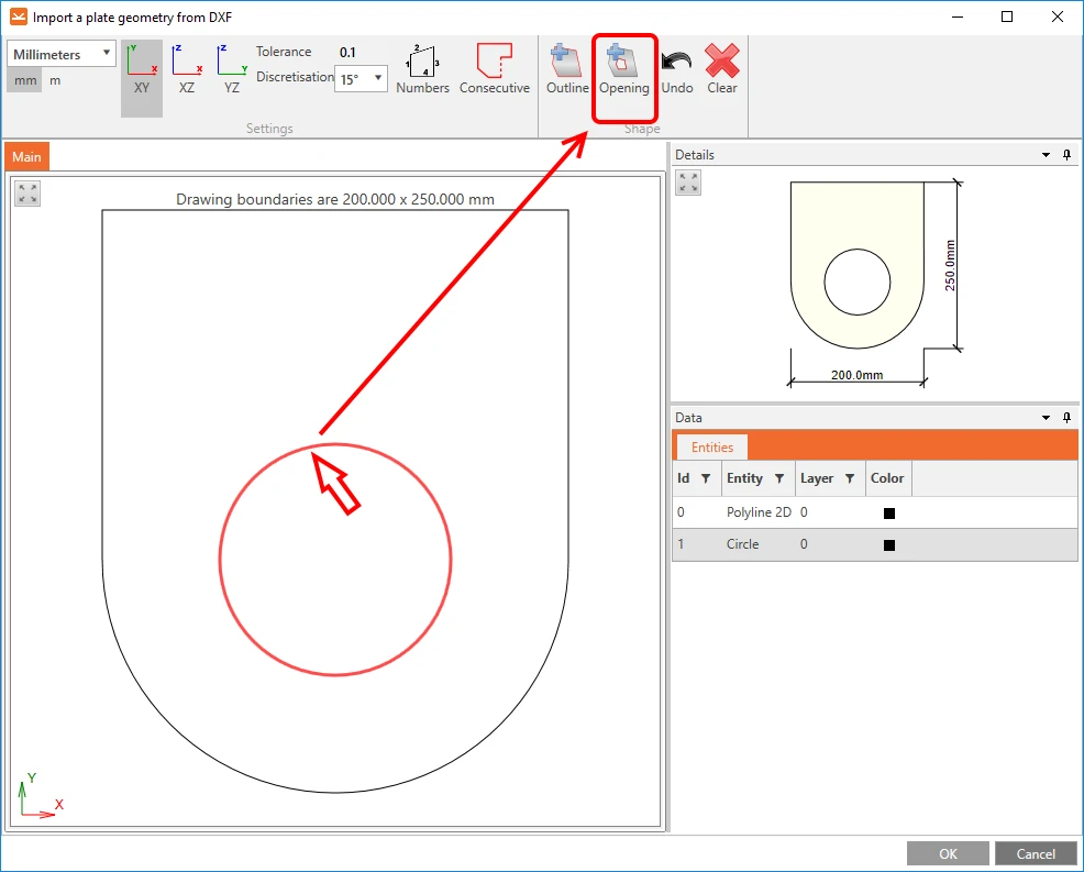
If there is an opening in the plate, pick the closed curve of the opening outline and click the command Opening.
DXF

To finish the import process, click OK.

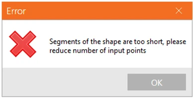
Limiting short lines in DXF imports (in 23.1.2 version)

Limiting short lines in DXF imports prevents issues during mesh generation and avoids any interruptions in analysis caused by excessively short lines. The minimum distance between two points is checked against a set limit, which is defined as 1/50 of the bounding box of the cross-section.

Read more in the release notes article: Limiting short lines in DXF imports.
Released in IDEA StatiCa patch 23.1.2.

Defining the insertion point (in version 24.0.2)

Defining the insertion point of a plate imported from a DXF file improves the accuracy of its placement within the model. Users can determine the insertion point, allowing for precise positioning of complex shapes and a more efficient workflow during DXF integration.

Selecting the insert point

There is an option in the DXF import process that allows users to set the insertion point based on:

  • DXF Origin: Uses the origin point as defined in the DXF file (default setting).
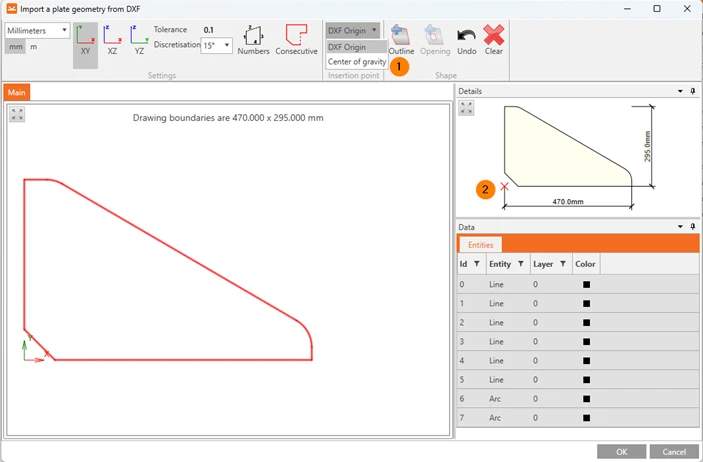
  • Center of gravity: Positions the insertion point at the center of the shape’s mass.
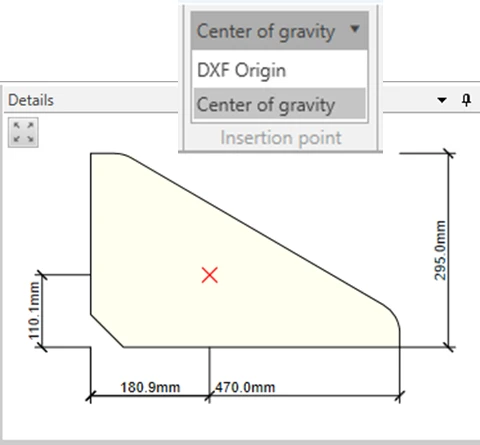
These options enable better control over the placement of imported shapes. The insertion point is displayed with a red cross in the DXF editor, alongside basic shape dimensions, providing users with a clear view of the real position before importing the shape into the model.

Enhanced Arc Import Process

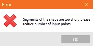
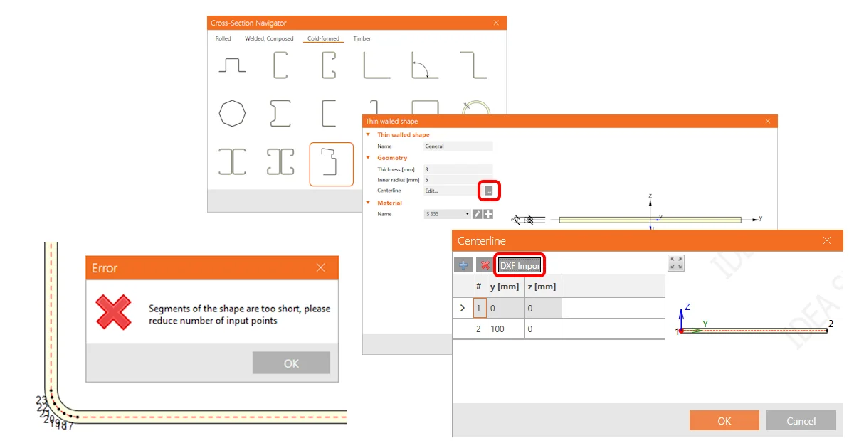
The arc import method has been improved to address issues encountered with the previous approach. Earlier, arcs were converted into polygons composed of short line segments, often resulting in small edges that caused import errors. Users frequently had to adjust these shapes manually in software like AutoCAD to avoid such errors. The updated method allows arcs to be imported directly, maintaining their true form and eliminating the problem of small edges, which reduces the need for manual adjustments.
Released in IDEA StatiCa patch 24.0.2.

Try out the new features of IDEA StatiCa today

Download the latest version for free

Related articles

Release notes IDEA StatiCa 24.1
  • Steel
  • Concrete
  • v24.1
  • +3
  • Steel
  • Concrete
  • v24.1

Release notes

Release notes IDEA StatiCa 24.1

Read more
Limiting short lines in imported DXF
  • Steel
  • DXF
  • Cross-sections
  • v24.0
  • v23.1
  • +5
  • Steel
  • DXF
  • Cross-sections
  • v24.0
  • v23.1

Knowledge base

Limiting short lines in DXF imports

Read more
Mesh generation error for a plate imported from DXF
  • Steel
  • Connection
  • Bolts
  • Modeling
  • Plates
  • +5
  • Steel
  • Connection
  • Bolts
  • Modeling
  • Plates

Knowledge base

Mesh generation error for a plate imported from DXF

Read more
How to create and use a custom cross-section
  • Steel
  • Connection
  • AISC (USA)
  • Geometry
  • Cross-sections
  • DXF
  • EN (Eurocode)
  • Modeling
  • +8
  • Steel
  • Connection
  • AISC (USA)
  • Geometry
  • Cross-sections
  • DXF
  • EN (Eurocode)
  • Modeling

Knowledge base

How to create and use a custom cross-section

Read more