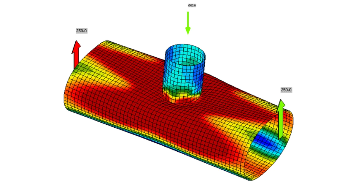
The model of the connection is greatly improved by the insertion of the condensed element. This element is added behind the member end and has the same properties as the elastic shell model of the member. It is just one element but it allows any elastic deformation and stress to develop in the member ends. Because of this, the part of the member consisting of shell elements may be shorter and still even improve the model behavior. The default length of both open and hollow sections modeled by shell elements is decreased to 1.25 × the larger of the cross-section outer dimensions. The length of the condensed element is 4 × the larger of the cross-section outer dimensions (the superelement is not visible for the end-user). The only difference is for linear buckling and stiffness analyses where the length of the condensed element is 0.5 × the larger of the cross-section outer dimensions. The reason is to keep the buckling mode shapes in the internal plates of the connection rather than in members.
The main benefits of this change are:
- 30 % faster calculation times (in average on a large number of projects)
- Faster visualization of results
- More accurate modeling of connections of hollow sections
This change was originally made to improve the analysis of connections of hollow sections, but the benefits are here for all models.
What are the main consequences? Some results change between versions, nevertheless, IDEA StatiCa runs a large number of automated tests. In the vast majority, the difference in results was below 1 %. However, in some cases, the differences are bigger. These cases are:
Cross-section deforms at the end of the shell model
This effect was the main reason the change was made. The cross-section may now deform at the ends of the model consisting of shell elements. Joints of hollow sections require relatively long members – up to 10 times cross-section diameter. Otherwise, the boundary conditions may affect the load resistance of the joint. By introducing condensed element behind the part of the model consisting of shell elements, the calculation is much faster with the same precision.
Note that the condensed element has only elastic properties. Plastic strains should not reach the member ends. Otherwise, they can affect the resistance of the connection.
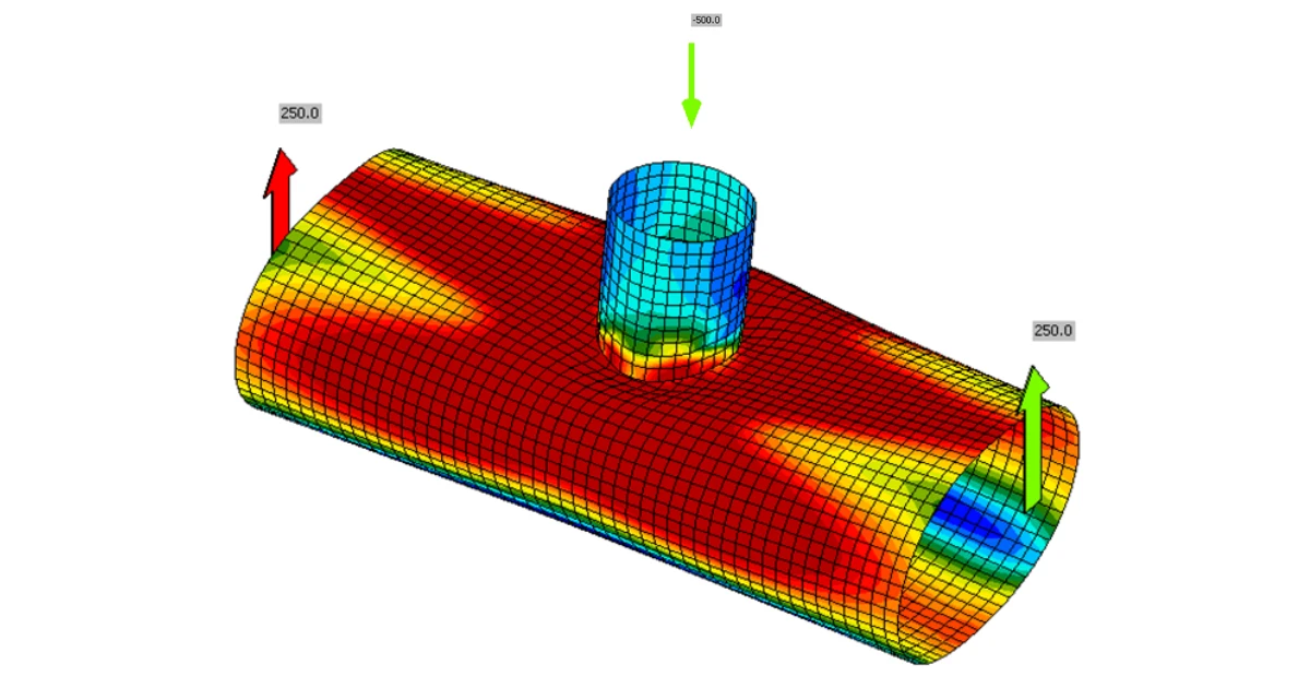
Shorter member stubs do not yield at the ends
This is an issue with, e.g., column brackets loaded heavily in shear by a force very close to the connection. By having shorter members, the bending moment at the member end is reduced.

If the member stub still fails in bending, the alternative solution is to model the member by the stiffening member and use a fictive member to apply the shear force.
Torsion
The warping was restrained by the multipoint constraints connecting the node with the beam end. These constraints are used to impose loads into the model. Now, the condensed element pushes the restraints further and the member is able to deform. This results in a bigger bimoment (warping moment) in the connection.

This is often the case for a one-sided joint of the secondary beam to the primary beam. Please note that the member design must be performed elsewhere and also that the bimoment caused by warping is very often neglected by the software packages but has to be taken into account. The warping resistance of open section members is surprisingly low.

Simplified loading / Loads in equilibrium
When using simplified loading and the continuous member is selected as bearing, the internal forces are different because the member lengths changed from 1.5 × h to (1.25 + 4) × h.
- Internal forces are different
- The column web panel in shear is loaded more heavily. Nevertheless, the loads in equilibrium option is necessary to correctly capture the behavior of continuous member.
The use of Loads in equilibrium is always recommended.

Shell bending resistance reduced for hollow sections
Load resistances of hollow section joints in the codes are determined by the Failure Mode Method that uses curve-fitting models determined from experiments and advanced numerical models. This design method is implemented in all codes. At the moment, the most recent state-of-the-art is in a draft of prEN 1993-1-8:2022. The real structure contains initial imperfections and residual stresses, which are not captured by shell models in IDEA StatiCa Connection. To achieve closer compliance with the results of codes, the influence of residual stress and initial imperfections was introduced in IDEA StatiCa models by reducing the bending resistance of shells of hollow sections with a high D/(2t) ratio. This allows to reduce the resistance of failure modes of joints but keep the normal and bending resistance of hollow section members. The reduction in plastic resistance of shell elements depends on the factor :

These combined changes allowed us to achieve close agreement with the results of the Failure Mode Method (FMM) contained in design codes. The compliance between IDEA StatiCa Connection and FMM is shown in the following figures.

Circular hollow sections
T-joint, normal force, angle


T-joint, in-plane bending moment, angle


T-joint, out-of-plane bending moment, angle


Y-joint, normal force, angle


Y-joint, in-plane bending moment, angle


Y-joint, out-of-plane bending moment, angle


X-joint, normal force, angle


X-joint, normal force, angle


X-joint, normal force, angle


K-joint, normal force, angle


Square hollow sections
T-joint, normal force, angle
Note that the reduction in resistance due to load in the chord is not accounted for in the FFM model. That is the explanation for the difference in results.


T-joint, in-plane bending moment, angle


T-joint, out-of-plane bending moment, angle


Y-joint, normal force, angle
Note that the reduction in resistance due to load in the chord is not accounted for in the FFM model. That is the explanation for the difference in results.


Y-joint, normal force, angle
Note that the reduction in resistance due to load in the chord is not accounted for in the FFM model. That is the explanation for the difference in results.


X-joint, normal force, angle


X-joint, normal force, angle


X-joint, normal force, angle


K-joint, normal force, angle