Idea Statica
  • Steel
  • Concrete
  • Support & Learning
  • Pricing
  • Company
  • Steel overview
  • Connection design
  • Member design
  • Parametric design
  • Steel case studies
  • Concrete overview
  • Walls and D-regions
  • Anchoring design
  • Concrete case studies
  • BIM Overview
  • Supported integrations
  • Checkbot
  • Viewer
  • APIs
  • Support Center
  • E-learning & certification
  • Blog
  • Downloads & Licensing
  • Plans
  • Free community tool
  • Enterprise customers
  • Students & educators
  • How much will you save?
  • About us
  • Contact
  • Research & development
  • Authorized resellers
  • Meet our customers
  • Career
  • Steel
    Steel overviewConnection designMember designParametric designSteel case studies
  • Concrete
    Concrete overviewWalls and D-regionsAnchoring designConcrete case studies
  • BIM OverviewSupported integrationsCheckbotViewerAPIs
  • Support & Learning
    Support CenterE-learning & certificationBlogDownloads & Licensing
  • Pricing
    PlansFree community toolEnterprise customersStudents & educatorsHow much will you save?
  • Company
    About usContactResearch & developmentAuthorized resellersMeet our customersCareer
14-Day Trial
14-Day Trial

Subscribe to our newsletter

Company

  • About us
  • Partners
  • Careers
  • Patent

Resources

  • Customer projects
  • Case studies
  • Connection Library
  • Verification books

Legal

  • EULA
  • Privacy policy
  • California Privacy
  • TOS Viewer
  • Licensing

Help

  • Contact
  • Quote request
  • Resellers
  • Downloads
FacebookInstagramLinkedInYouTube

© IDEA StatiCa 2009-2026

Trusted and used worldwide by engineers, fabricators & consultants.

Support CenterKnowledge Base ArticlesLoad effects displayed in the scene
Advanced analysis types for your steel structures
Nonconformity in connection analysis results
Connection analysis 0% or doesn't reach 100%
What is the singularity warning?
Stop at limit strain
Torsion moments and warping
Warping of members – Load in shear center
Thin-walled (cold-formed) members
Load effects displayed in the scene
SteelConnection designKnowledge basev25.0Load effects

Load effects displayed in the scene

This article is also available in
ENCZDEESFRITPTNLHUROKRPLTHTRVIZH

To assist when reviewing the results, the calculated load effects are displayed in the scene in the Check tab. This helps engineers select the results for a particular calculated load effect.

When more than one load effect is used, users can check what effect every single load effect in the structure has in the results. This can help users to understand the overall results that are presented. 

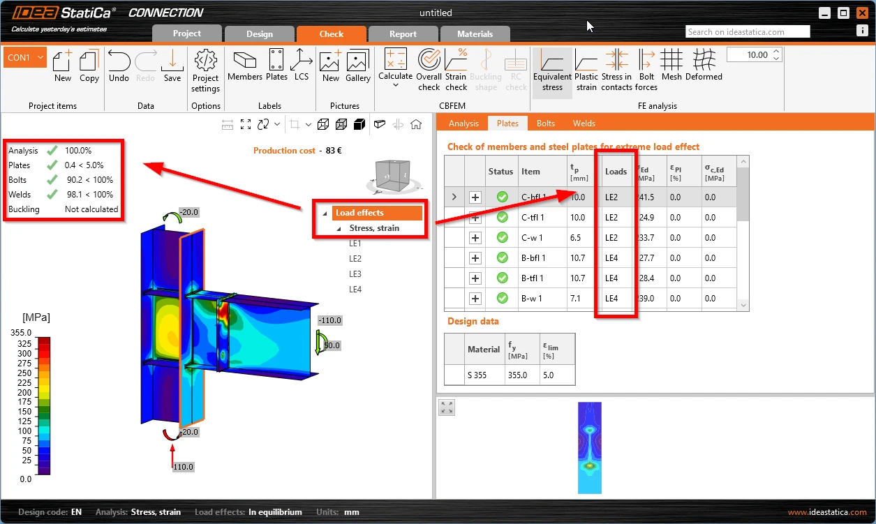
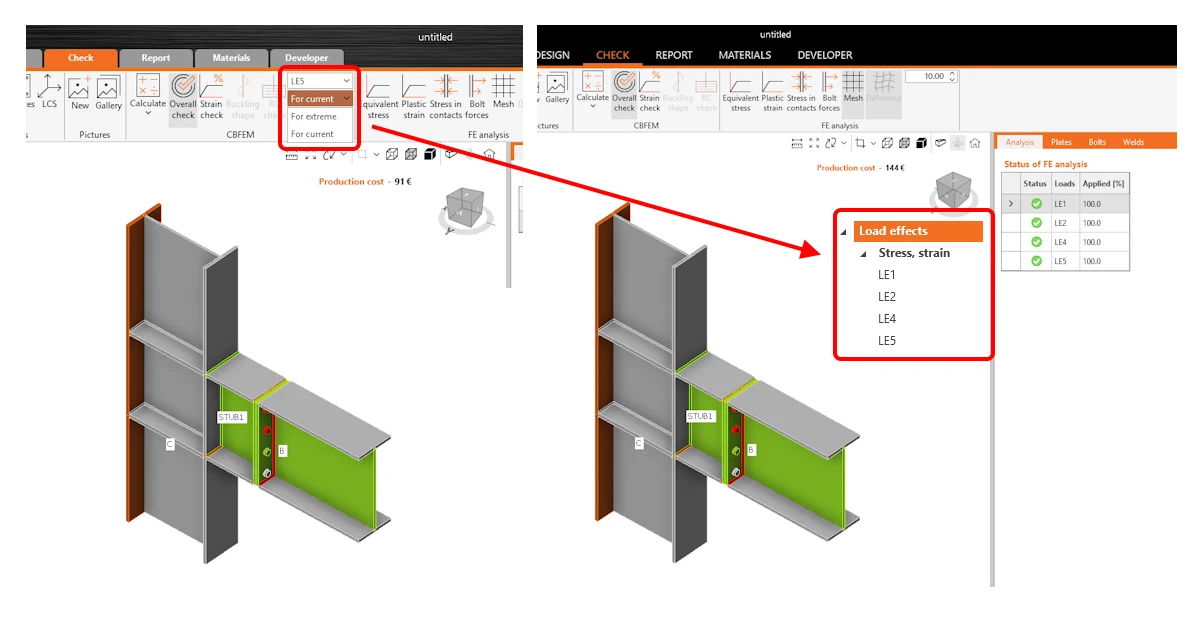
For easier orientation, all calculated load effects are shown directly in the tree in the scene under the Check tab, so users can quickly choose the load effect and check the results for the selected one.
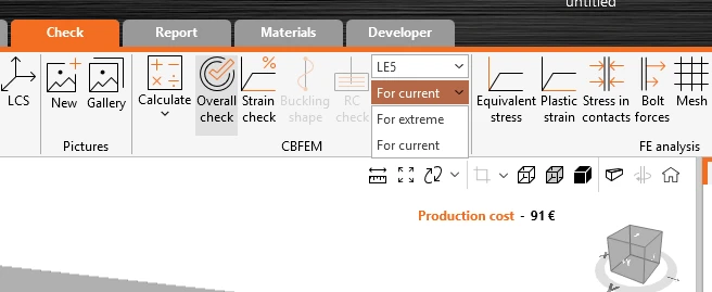
Load effects displayed in the scene

The calculated load effects are available directly in the tree in the 3D scene. Disabled load effects in the Design tab are not shown in the Check tab tree.

When the main Load effects header (or the Stress, strain item under) is selected, the results show a mix of all load effects, while for each connection part, there can be a different critical load effect. These results are shown:

  • in brief results
  • in the scene (stress maps)
  • in the check tables
Load effects displayed in the scene

When a specific load effect is selected, results for this load only are shown everywhere – in the result overview, in the scene, and in tables.
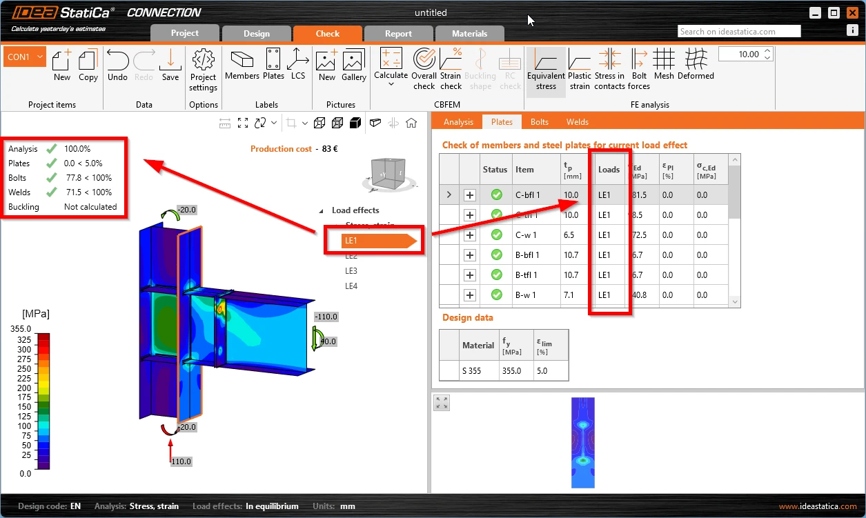
Load effects displayed in the scene

Take the latest version of IDEA StatiCa for a test drive today

Get 14 days of full access, completely free.

Check out IDEA StatiCa for free
Related articles

Release notes IDEA StatiCa 25.0
  • Steel
  • Concrete
  • v25.0
  • +3
  • Steel
  • Concrete
  • v25.0

Release notes

Release notes IDEA StatiCa 25.0

Read more
Nonconformity in connection analysis results
  • Steel
  • Connection
  • Load effects
  • +3
  • Steel
  • Connection
  • Load effects

Knowledge base

Nonconformity in connection analysis results

Read more
Connection analysis 0% or doesn't reach 100%
  • Steel
  • Connection
  • EN (Eurocode)
  • Overall check
  • Project settings
  • GMNA
  • AISC (USA)
  • v25.1
  • +8
  • Steel
  • Connection
  • EN (Eurocode)
  • Overall check
  • Project settings
  • GMNA
  • AISC (USA)
  • v25.1

Knowledge base

Connection analysis 0% or doesn't reach 100%

Read more
Stop at limit strain
  • Steel
  • Connection
  • AISC (USA)
  • Overall check
  • Project settings
  • Stress/strain
  • EN (Eurocode)
  • CBFEM
  • Modeling
  • +9
  • Steel
  • Connection
  • AISC (USA)
  • Overall check
  • Project settings
  • Stress/strain
  • EN (Eurocode)
  • CBFEM
  • Modeling

Knowledge base

Stop at limit strain

Read more