Idea Statica
  • Steel
  • Concrete
  • BIM & Workflows
  • Support & Learning
  • Pricing
  • Company
  • Steel overview
  • Connection design
  • Member design
  • Parametric design
  • Steel case studies
  • Concrete overview
  • Walls and D-regions
  • Anchoring design
  • Concrete case studies
  • BIM Overview
  • Supported integrations
  • Checkbot
  • Viewer
  • APIs
  • Support Center
  • E-learning & certification
  • Blog
  • Downloads & Licensing
  • Plans
  • Free community tool
  • Enterprise customers
  • Students & educators
  • How much will you save?
  • About us
  • Contact
  • Research & development
  • Authorized resellers
  • Meet our customers
  • Career
  • Steel
    Steel overviewConnection designMember designParametric designSteel case studies
  • Concrete
    Concrete overviewWalls and D-regionsAnchoring designConcrete case studies
  • BIM & Workflows
    BIM OverviewSupported integrationsCheckbotViewerAPIs
  • Support & Learning
    Support CenterE-learning & certificationBlogDownloads & Licensing
  • Pricing
    PlansFree community toolEnterprise customersStudents & educatorsHow much will you save?
  • Company
    About usContactResearch & developmentAuthorized resellersMeet our customersCareer
14-Day Trial
14-Day Trial
  • Steel
  • Concrete
  • BIM & Workflows
  • Support & Learning
  • Pricing
  • Company

Subscribe to our newsletter

Company

  • About us
  • Partners
  • Careers
  • Patent

Resources

  • Customer projects
  • Case studies
  • Connection Library
  • Verification books

Legal

  • EULA
  • Privacy policy
  • California Privacy
  • TOS Viewer
  • Licensing

Help

  • Contact
  • Quote request
  • Resellers
  • Downloads
FacebookInstagramLinkedInYouTube

© IDEA StatiCa 2009-2026

Trusted and used worldwide by engineers, fabricators & consultants.

Support CenterVerification examplesBending stiffness of welded joint of open sections
Bending stiffness of welded joint of open sections
SteelConnection designVerificationsConnectionCBFEM

Bending stiffness of welded joint of open sections

This article is also available in
ENCZDEESFRITPTNLHUROKRPLTHTRVIZH

This verification example contains chapter 10.1 of the book "Benchmark cases for advanced design of structural steel connections" written by prof. Wald and his team.

Description

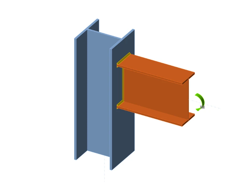
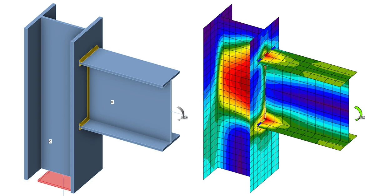
The prediction of rotational stiffness is described on a welded eaves moment joint. A welded joint of open section column HEB and beam IPE is studied, and the joint behavior is described on a moment-rotation diagram. The results of the analytical model by component method (CM) are compared with the numerical results obtained by the component-based finite element method (CBFEM). A benchmark case is available.

Analytical model

The rotational stiffness of a joint should be determined from a deformation of its basic components, which are represented by the stiffness coefficient ki. The rotational stiffness of the joint Sj is obtained from:

Sj=Ez2μΣi1kiS_j = \frac{E z^2}{\mu \Sigma_i \frac{1}{k_i}}Sj​=μΣi​ki​1​Ez2​

where:

  • ki  is the stiffness coefficient for the joint component i;
  • z   is the lever arm; see 6.2.7;
  • μ   is the stiffness ratio; see 6.3.1.

The joint components that are taken into account in this example are column web panel in shear k1, column web in compression k2, and column web in tension k3. The stiffness coefficients are defined in Table 6.11 in EN 1993-1-8:2005. The initial stiffness Sj,ini is obtained for a moment Mj,Ed ≤ 2/3 Mj,Rd.

Sj=E z21k1+1k2+1k3S_j = \frac{E \, z^{2}}{\frac{1}{k_1} + \frac{1}{k_2} + \frac{1}{k_3}}Sj​=k1​1​+k2​1​+k3​1​Ez2​

Sj,ini=Sj1.5ψS_{j,\text{ini}} = \frac{S_j}{1.5^{\psi}}Sj,ini​=1.5ψSj​​

where 

SjS_{j}Sj​ — rotational stiffness of the joint

ψ\psiψ = 2.7 — EN 1993-1-8 table 6.8

An open section beam IPE 400 is welded to a column HEB 300 in the example. Beam flanges are connected to the column flange with welds with the throat thickness of 9 mm. The beam web is connected with welds with the throat thickness of 5 mm. Plastic stress distribution is considered in welds. The material of the beam and column is S235. The design resistance is limited by the components column panel in shear and column panel in transverse compression . The calculated stiffness coefficients of the basic components, initial stiffness, stiffness by design resistance, and rotation of the beam are summarised in Tab. 10.1.1.

Tab. 10.1.1 Results of the analytical model\textsf{\textit{\footnotesize{Tab. 10.1.1 Results of the analytical model}}}Tab. 10.1.1 Results of the analytical model

Numerical model

Detailed information about the prediction of stiffness in CBFEM may be found in chapter 3.9. The same eaves moment joint is modeled, and the results are in Tab. 10.1.2. The design resistance is reached by 5% plastic strain in the component column web in tension. The CBFEM analyses allow calculating rotational stiffness at any stage of loading.

Experimental overview 

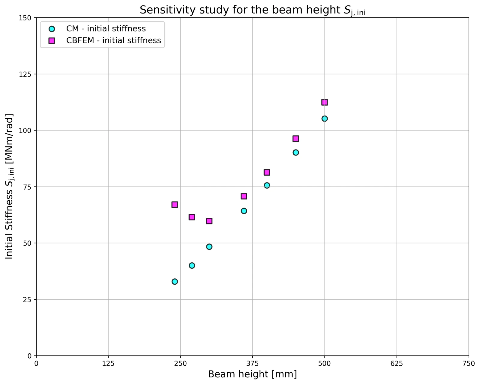
For the purpose of the comparison, a cross-section was set to HEB300 and the beam cross-section was variable. All materials utilised were S235. 
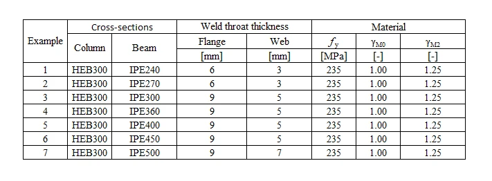
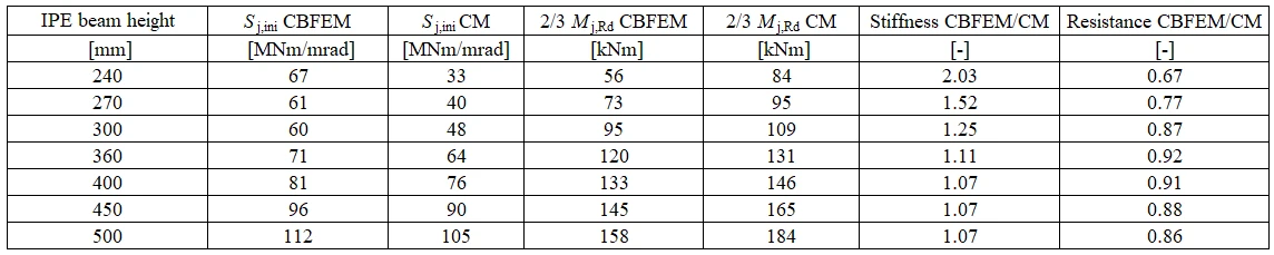
Tab. 10.1.2 Experimental overview\textsf{\textit{\footnotesize{Tab. 10.1.2 Experimental overview}}}Tab. 10.1.2 Experimental overview

Tab. 10.1.3 Experimental overview\textsf{\textit{\footnotesize{Tab. 10.1.3 Experimental overview}}}Tab. 10.1.3 Experimental overview

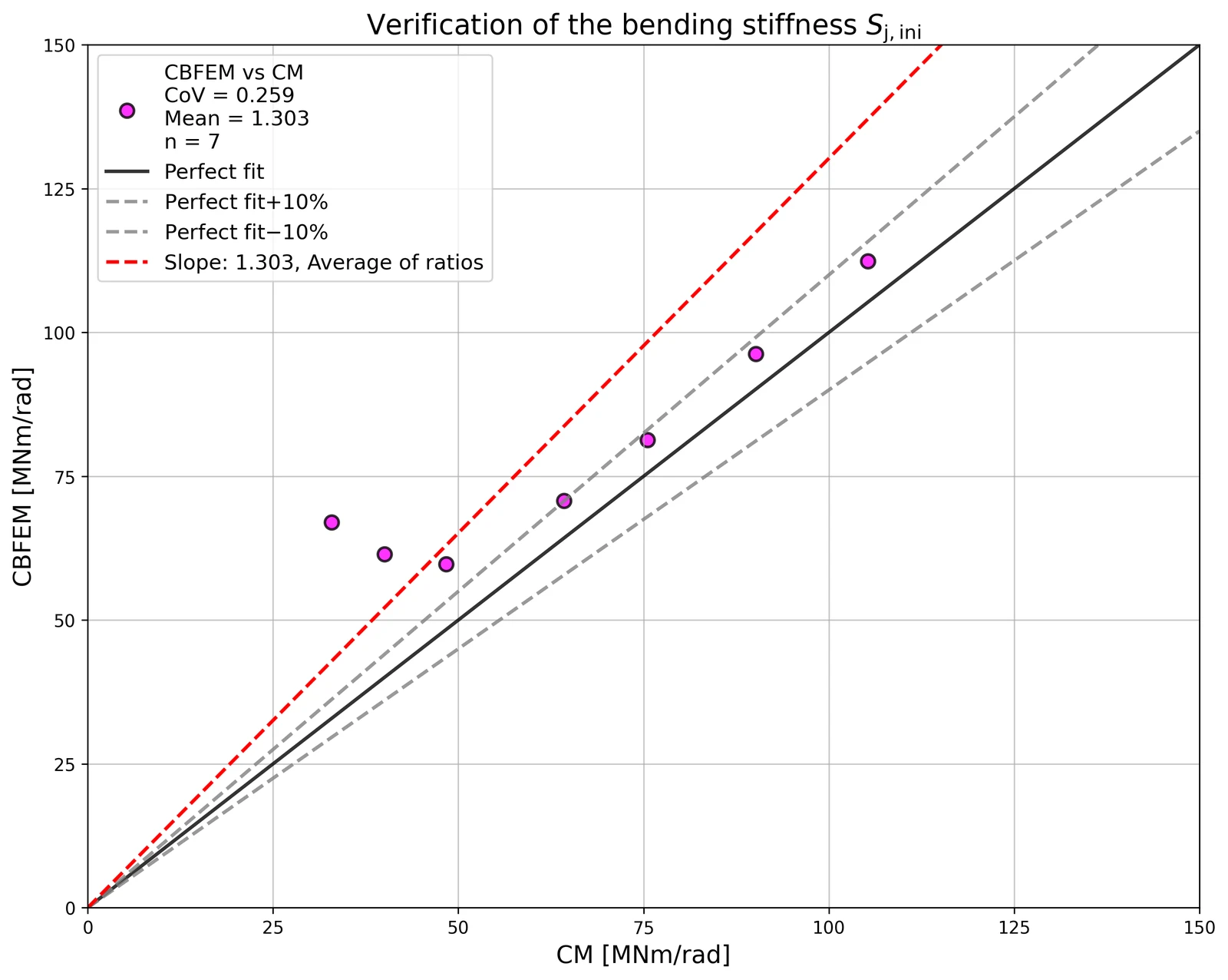
Fig. 1 Verification of CBFEM to CM\textsf{\textit{\footnotesize{Fig. 1 Verification of CBFEM to CM}}}Fig. 1 Verification of CBFEM to CM

Fig. 2Sensitivity study of beam IPE cross-section\textsf{\textit{\footnotesize{Fig. 2Sensitivity study of beam IPE cross-section}}}Fig. 2Sensitivity study of beam IPE cross-section

Verification of stiffness

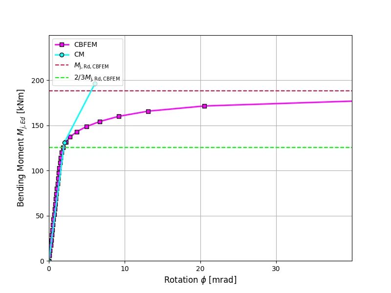
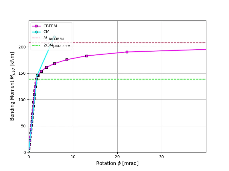
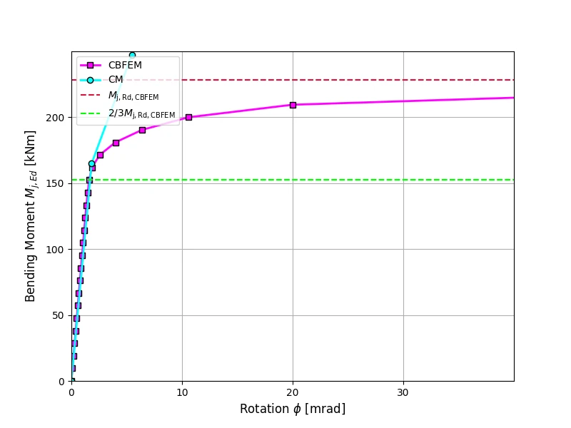
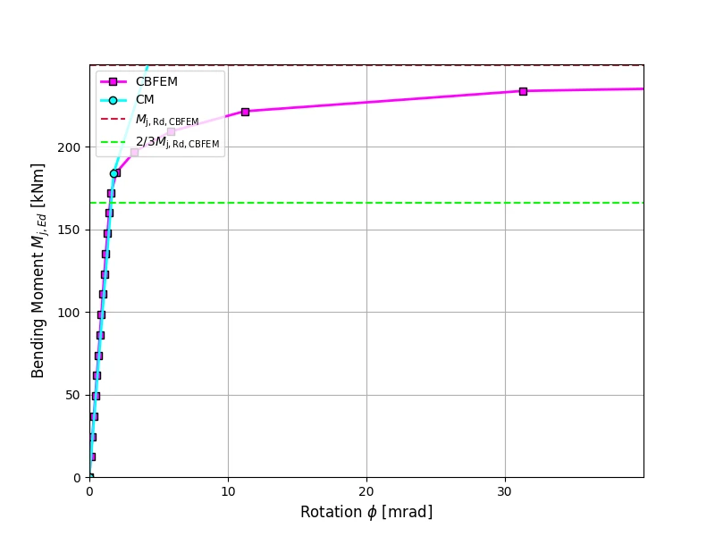
The rotational stiffness calculated by CBFEM is compared with CM. The comparison shows good agreement in initial stiffness and correspondence of joint behavior. The calculated stiffness from CBFEM and CM are summarised in Tab. 10.1.3.

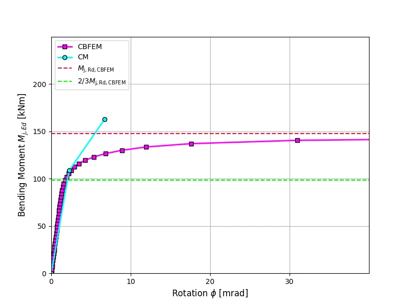
A comparison of the global behavior of a welded eaves moment joint described by a moment-rotation diagram is prepared. The joint is analyzed, and the stiffness of the connected beam is calculated. The main characteristic is the initial stiffness calculated at 2/3Mj,Rd, where Mj,Rd is the design moment resistance of the joint. The moment-rotation diagram is shown in Fig. 10.1.1.
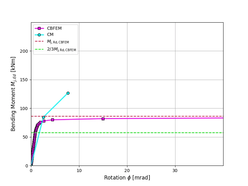
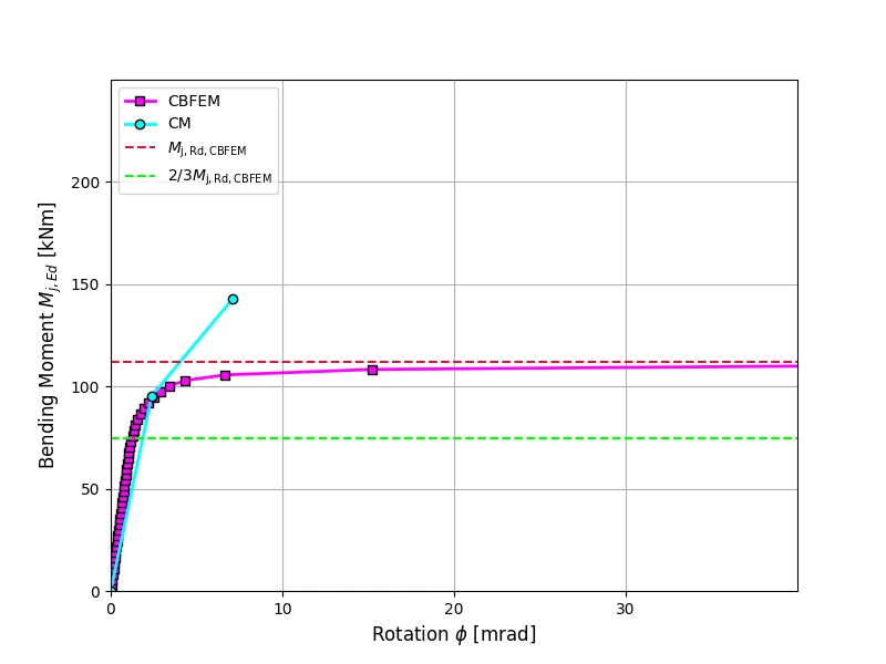
Fig. 3 Moment-rotation diagram for a welded eaves moment joint, IPE240\textsf{\textit{\footnotesize{Fig. 3 Moment-rotation diagram for a welded eaves moment joint, IPE240}}}Fig. 3 Moment-rotation diagram for a welded eaves moment joint, IPE240

Fig. 4 Moment-rotation diagram for a welded eaves moment joint, IPE270\textsf{\textit{\footnotesize{Fig. 4 Moment-rotation diagram for a welded eaves moment joint, IPE270}}}Fig. 4 Moment-rotation diagram for a welded eaves moment joint, IPE270

Fig. 5 Moment-rotation diagram for a welded eaves moment joint, IPE300\textsf{\textit{\footnotesize{Fig. 5 Moment-rotation diagram for a welded eaves moment joint, IPE300}}}Fig. 5 Moment-rotation diagram for a welded eaves moment joint, IPE300

Fig. 6 Moment-rotation diagram for a welded eaves moment joint, IPE360\textsf{\textit{\footnotesize{Fig. 6 Moment-rotation diagram for a welded eaves moment joint, IPE360}}}Fig. 6 Moment-rotation diagram for a welded eaves moment joint, IPE360

Fig. 7 Moment-rotation diagram for a welded eaves moment joint, IPE400\textsf{\textit{\footnotesize{Fig. 7 Moment-rotation diagram for a welded eaves moment joint, IPE400}}}Fig. 7 Moment-rotation diagram for a welded eaves moment joint, IPE400

Fig. 8 Moment-rotation diagram for a welded eaves moment joint, IPE450\textsf{\textit{\footnotesize{Fig. 8 Moment-rotation diagram for a welded eaves moment joint, IPE450}}}Fig. 8 Moment-rotation diagram for a welded eaves moment joint, IPE450

Fig. 9 Moment-rotation diagram for a welded eaves moment joint, IPE500\textsf{\textit{\footnotesize{Fig. 9 Moment-rotation diagram for a welded eaves moment joint, IPE500}}}Fig. 9 Moment-rotation diagram for a welded eaves moment joint, IPE500

Benchmark case

Inputs

Beam and column

  • Steel S235
  • Column HEB 300
  • Beam IPE 400
  • Flange weld throat thickness af  = 9 mm
  • Web weld throat thickness aw  = 5 mm
  • Column offset s = 150 mm
  • Double fillet weld

Outputs

  • Design resistance Mj,Rd=199kNmM_\mathrm{j,Rd}= 199 \quad \mathrm{kNm}Mj,Rd​=199kNm
  • Load Mj,Ed=2/3Mj,Rd=133kNmM_\mathrm{j,Ed}=2/3M_\mathrm{j,Rd}= 133\quad \mathrm{kNm}Mj,Ed​=2/3Mj,Rd​=133kNm 
  • Secant rotational stiffness Sj,ini=81.3MNm/radS_\mathrm{j,ini}= 81.3\quad \mathrm{MNm/rad}Sj,ini​=81.3MNm/rad 

Fig. 10 Benchmark case for welded eaves moment joint (IPE 400 to HEB 300)\textsf{\textit{\footnotesize{Fig. 10 Benchmark case for welded eaves moment joint (IPE 400 to HEB 300)}}}Fig. 10 Benchmark case for welded eaves moment joint (IPE 400 to HEB 300)

Open in ViewerDownload