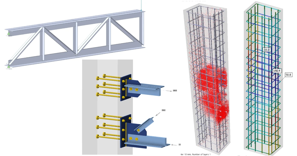


About the Truss structures
The global model is predominantly built up from truss elements that cover only tension/compression. It means that bending and shear in the members are completely suppressed. From an FEM perspective, the stiffness matrix is dominated by axial terms, eliminating bending and shear DOFs (Degrees of freedom).
- Convert bending to axial forces
- Maximize material utilization
- Provide clear load paths
- Enable long spans
- Simplify stability assessment
Global model
The cantilevered truss system is fixed to the prefabricated concrete column. The truss structure is coupled with a beam via a pair of pinned connections. All forces are transferred through anchors in tension and shear, and concrete under compression.
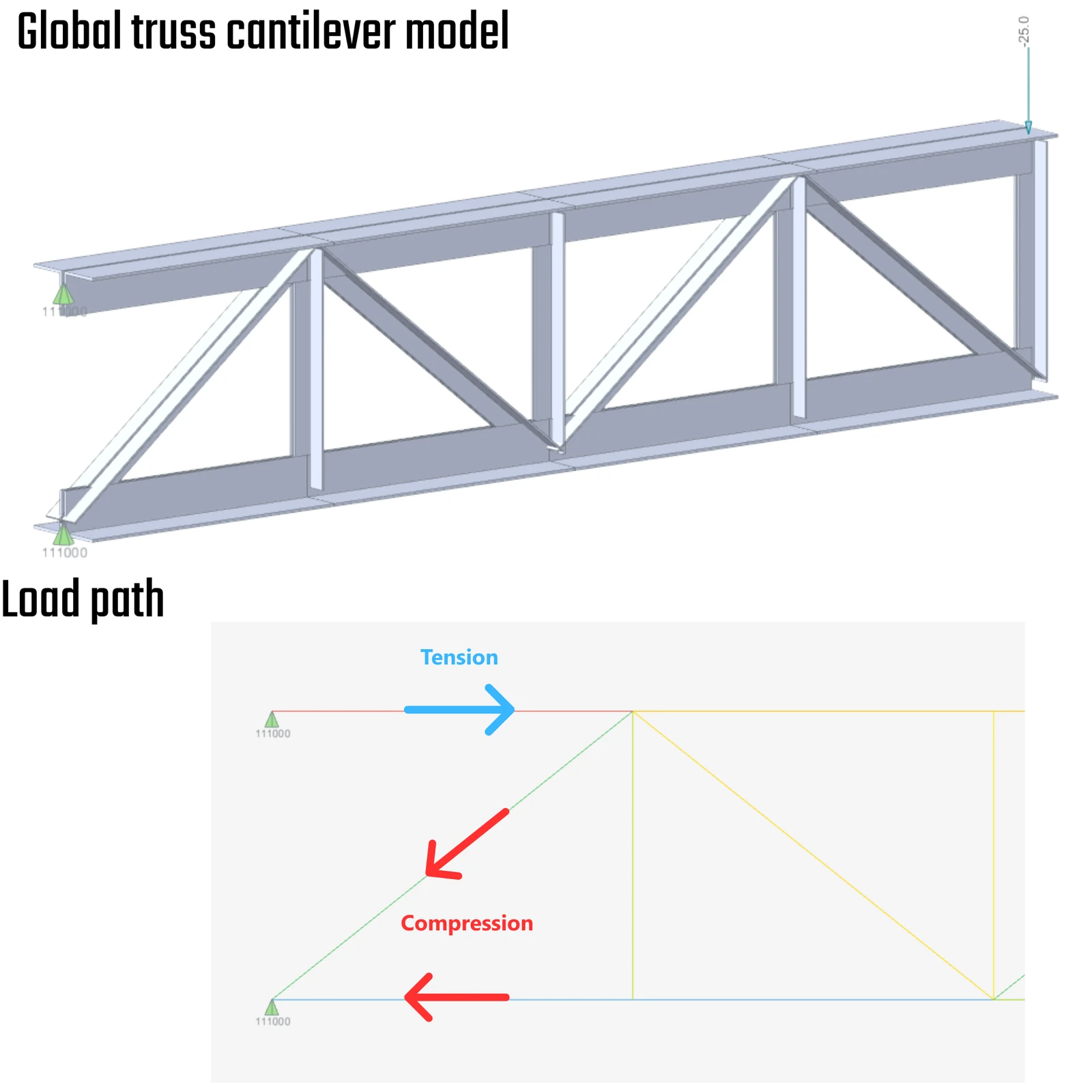
01) Global truss model and clear load path
Checkbot
These types of structures are imported into Checkbot with paired or multiple nodes that, by their nature, cannot be exported to IDEA StatiCa Connection in a set. In the first step, the top-chord node will be deleted. The top-chord member will be unrelated to any existing node and must be connected to the bottom-chord node, which merges the diagonal and bottom-chord members. Once the process is complete, all members will be unified under one prime node. It opens the way to more effectively control more members with the offset assembly.
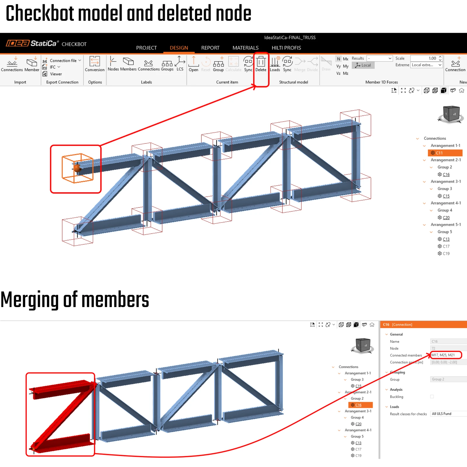
02) Checkbot model + merging of members into one node
IDEA StatiCa Connection
The constructed model comprises a sequence of double L-profiles. The upper and lower chords of the truss are connected to the precast column through cast-in-place washer plates, complemented by a base plate and pre-welded gusset plate to facilitate efficient assembly at the construction site.
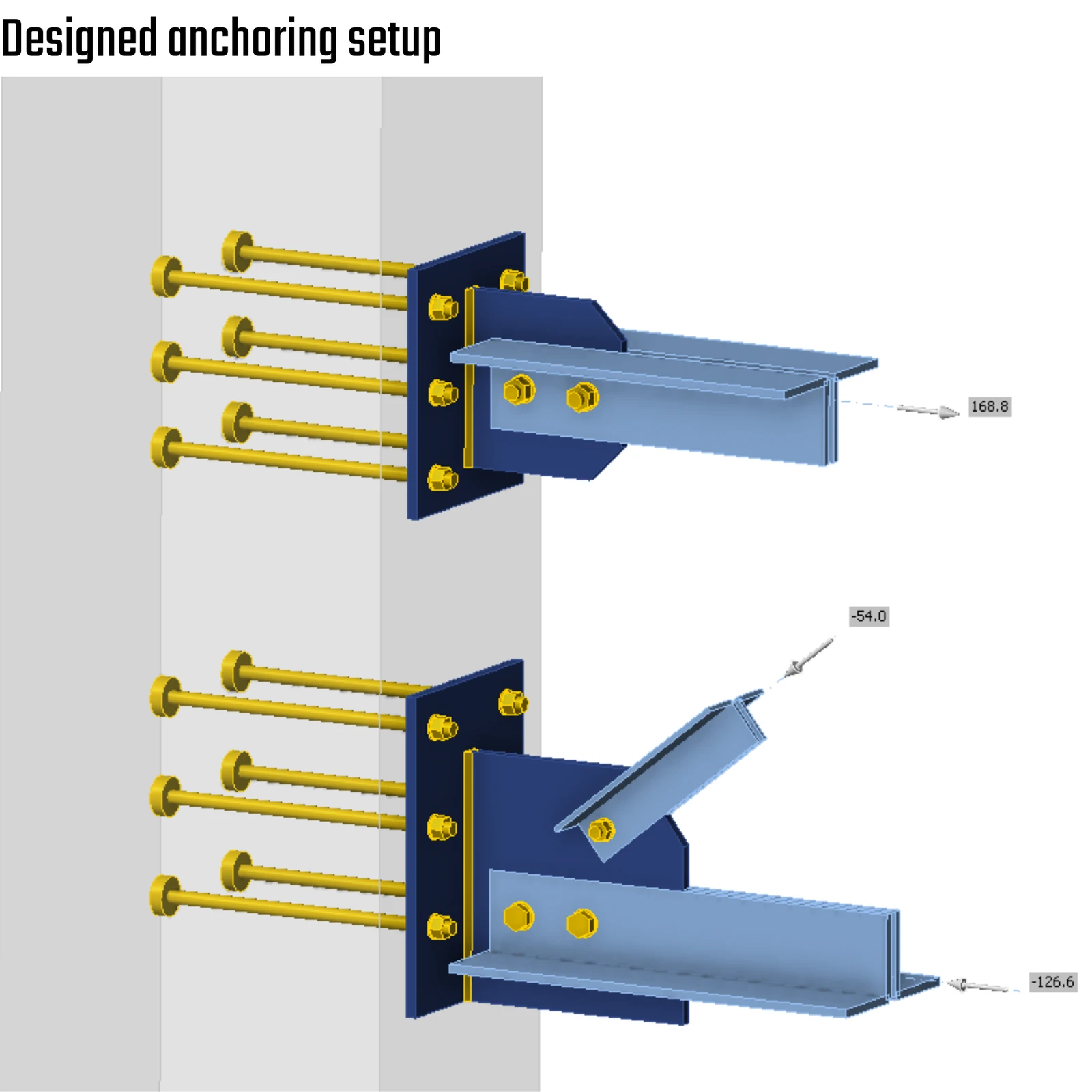
03) Designed anchoring model description
In global analysis, axial forces are typically assumed to act through the cross-section's centroid. However, if the bolt group in the real connection is not aligned with the section’s center of gravity, an eccentricity is introduced. This eccentricity generates secondary bending moments in the connected members.
Such effects are not captured in a standard global FEA model unless the connection geometry and load introduction are modeled explicitly. In practice, the additional moment from axial force eccentricity manifests as increased bending stress, which subsequently contributes to the final von Mises stress evaluation in the detailed connection assessment.
For the investigated truss configuration, the N–Vy–Vz constraint provides a more realistic representation of force transfer. This statement is not intended as a universal recommendation for all truss systems, but rather as a conclusion specific to this structural arrangement.
These constraints suppress rotational deformation at the joint, resulting in residual reaction moments. Furthermore, the vertical diagonal restrains chord bending, reinforcing the assumption that the N–Vy–Vz constraint better reflects the actual connection behavior in this case.
From a connection mechanics perspective, this boundary condition is therefore considered closer to physical reality.
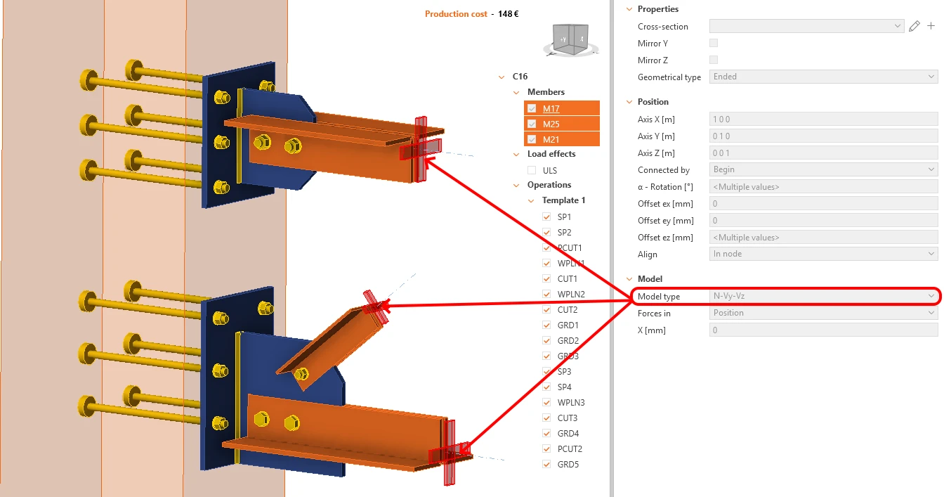
04) Constrained chords and diagonals
The wire model illuminates the trajectories of the loads and the center-of-gravity lines for each section.
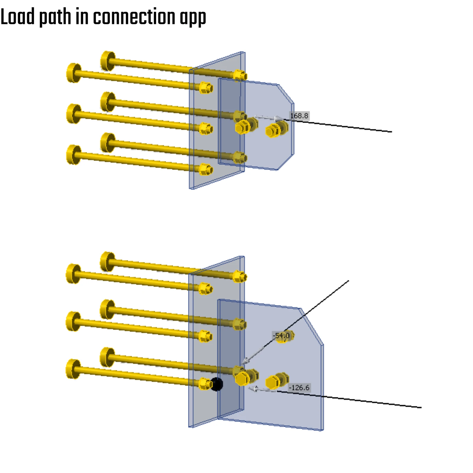
05) Wire model and clear load path
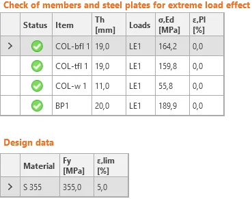
The deformed shape and stress visualisations provide insight and a sanity check on whether the loads are correctly applied. The tension in the top chord and compression in the bottom chord indicate that the surrogated model works well.
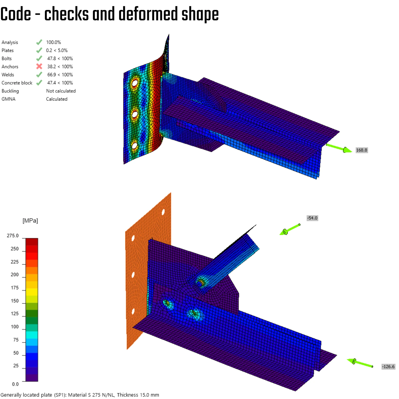
06) Code-checks and deformed shape
The interaction of forces is not accounted for in the concrete block due to simplified assumptions that are valid for the concrete medium in the Connection app. The utilization is only 38%, and the anchor check fails. Why does this happen?
FYI:
Anchor groups at separate base plates interact with each other in one concrete block. This is out of the scope of standards for anchorage design. Concrete breakout in tension and concrete pryout are not checked. Concrete edge failure is not checked. (CEB-FIB: Bulletin 58 - Design of anchorages in concrete (2011) – Chapter 1.2: Figure 1.2-8 and Figure 1.2-9) .
It navigates the user to the 3D Detail code-check because the code is short on the aforementioned setup.
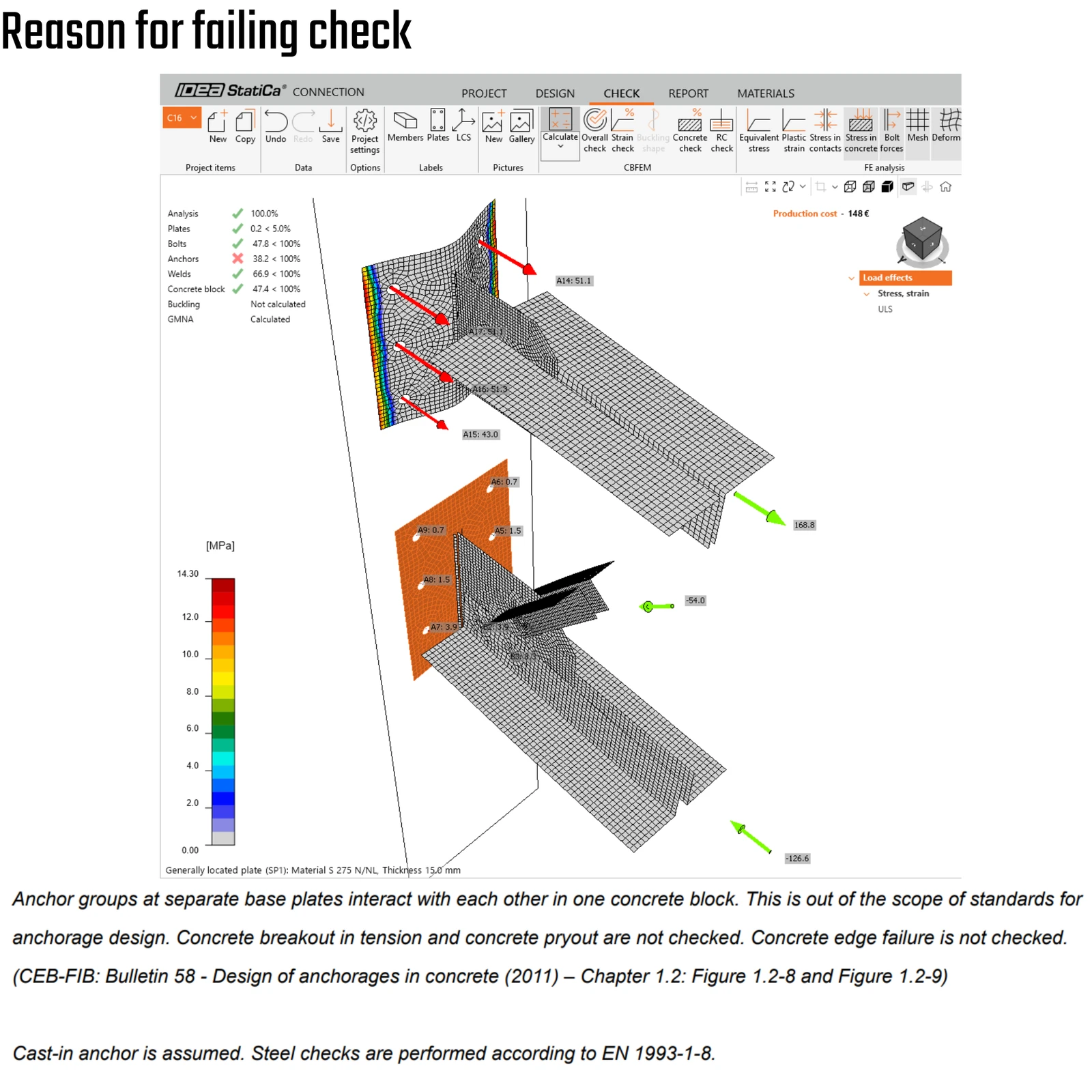
07) Why does it fail on the anchors?
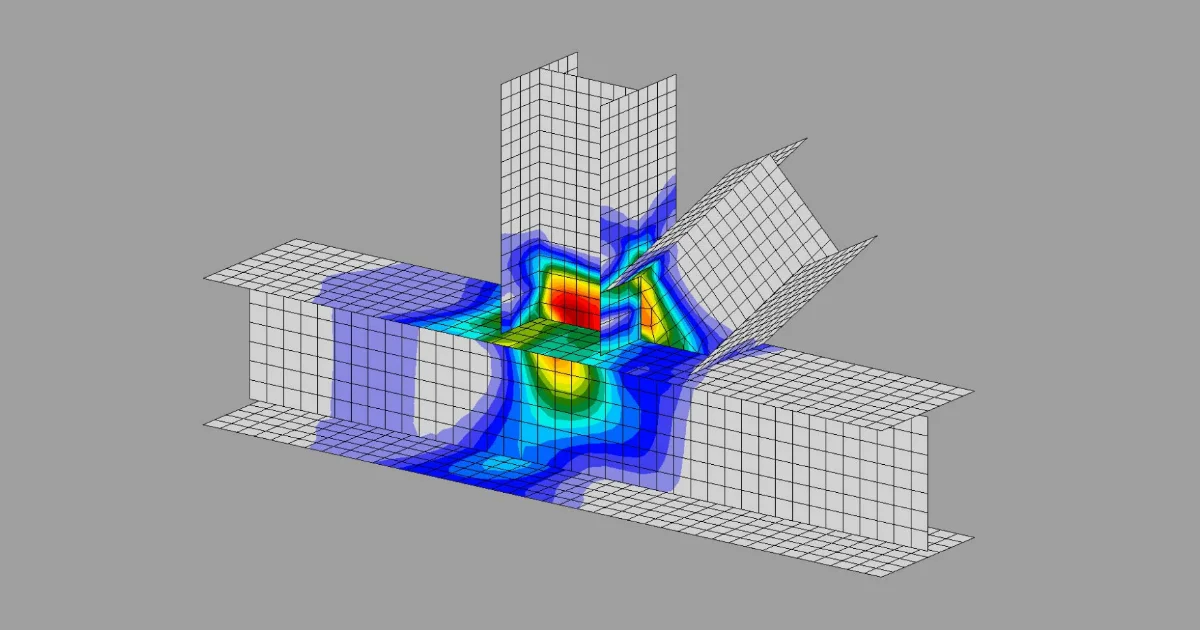
Buckling should always be checked when the connection is examined. The mode shape and buckling factor are provided as indicators of the safety margin, and the mode most likely to become unstable first can be identified.
This relates to linear buckling analysis, in which the contact between the gusset plate and the walls of the double L-sections is opened.
Open contact (gap):
If plates are separated in the equilibrium state:
- The contact is inactive
- No stiffness contribution is added
- Surfaces move independently in the buckling mode
Consequences of practical steel connections:
In many steel connections:
- gusset plates
- angles
- bolt holes
- washers
Contacts are only partially active in the equilibrium state.
Therefore, in LBA:
- Only currently compressed zones contribute stiffness
- Potential future contacts are ignored
This may lead to:
- local penetration in eigenmodes
- over-flexible buckling modes
- unrealistic deformation patterns.
This is not a bug — it is a fundamental limitation of eigenvalue buckling with contact.
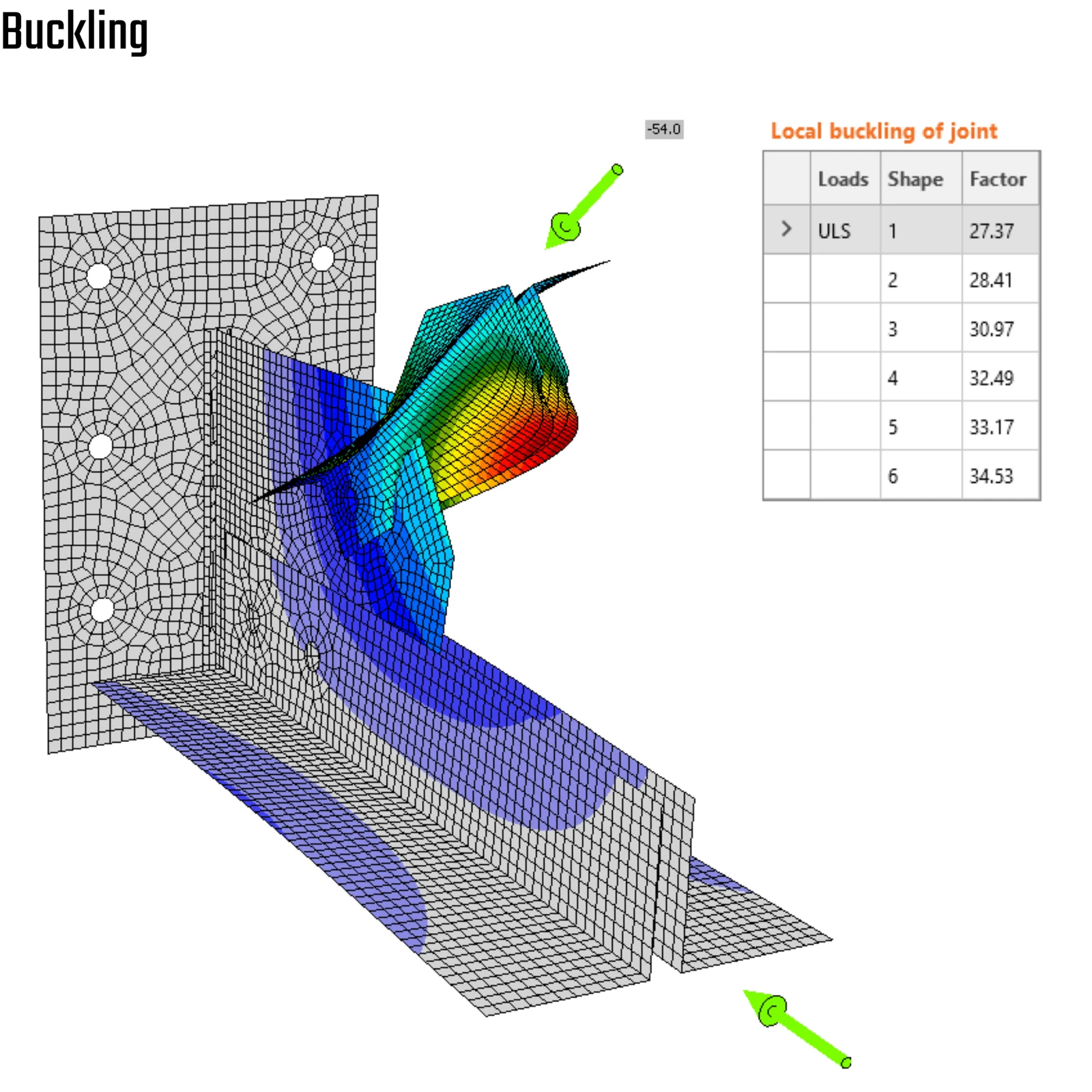
08) Linear buckling modes and critical factor
IDEA StatiCa 3D Detail
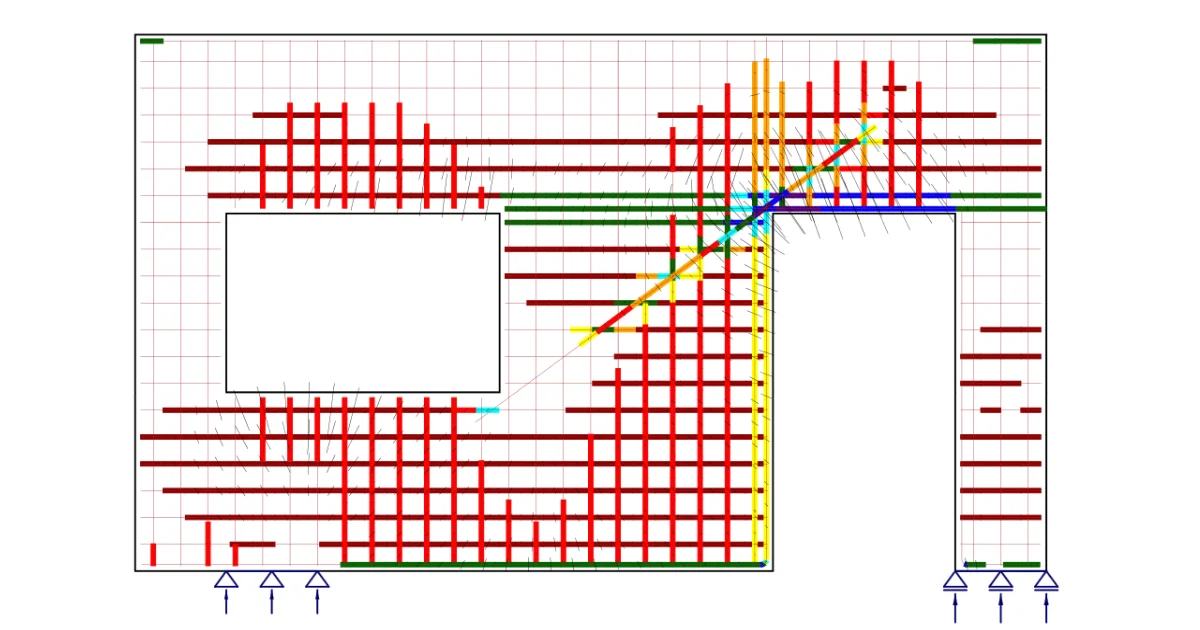
To close the design loop and achieve a satisfactory solution for all components — including the precast concrete column — it is essential to account for the existing reinforcement layout and assess the system considering the interaction between anchors and reinforcing bars.
The load transfer mechanism does not end at the base plate. Anchor forces must be redistributed into the reinforced concrete member through bond, confinement, and strut-and-tie action. Therefore, the reinforcement must be explicitly included in the verification model.
Using the BIM link from IDEA StatiCa Connection, the data transfer is straightforward and efficient. The following information can be imported directly:
- Geometry of the concrete column
- Base plate and anchor configuration
- Resulting forces in anchors and welds
This significantly accelerates the path toward final code verification.
However, to obtain a physically consistent assessment, the mandatory components — particularly the reinforcement layout and realistic boundary conditions — must be defined in the 3D Detail model (CSFM). Only then can the composite behavior of concrete and reinforcement be evaluated correctly, and brittle failure modes (e.g., concrete breakout) be assessed in the context of a reinforced system.
The system of predefined force vector field, derived from the connection app, guarantees the meaningful redistribution of the stresses under the base plate.
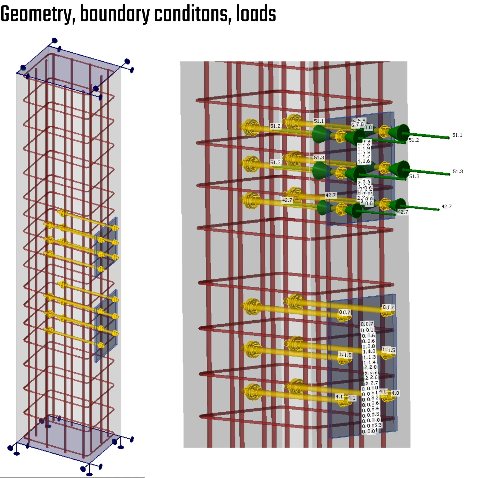
09) Reinforcements, boundary conditions + force distribution
It is necessary to perform a sanity check and a visual inspection to ensure the model behaves as expected. The compressive stress flow exhibits the expected behavior, and the reinforcement stress ensures the design's safety.
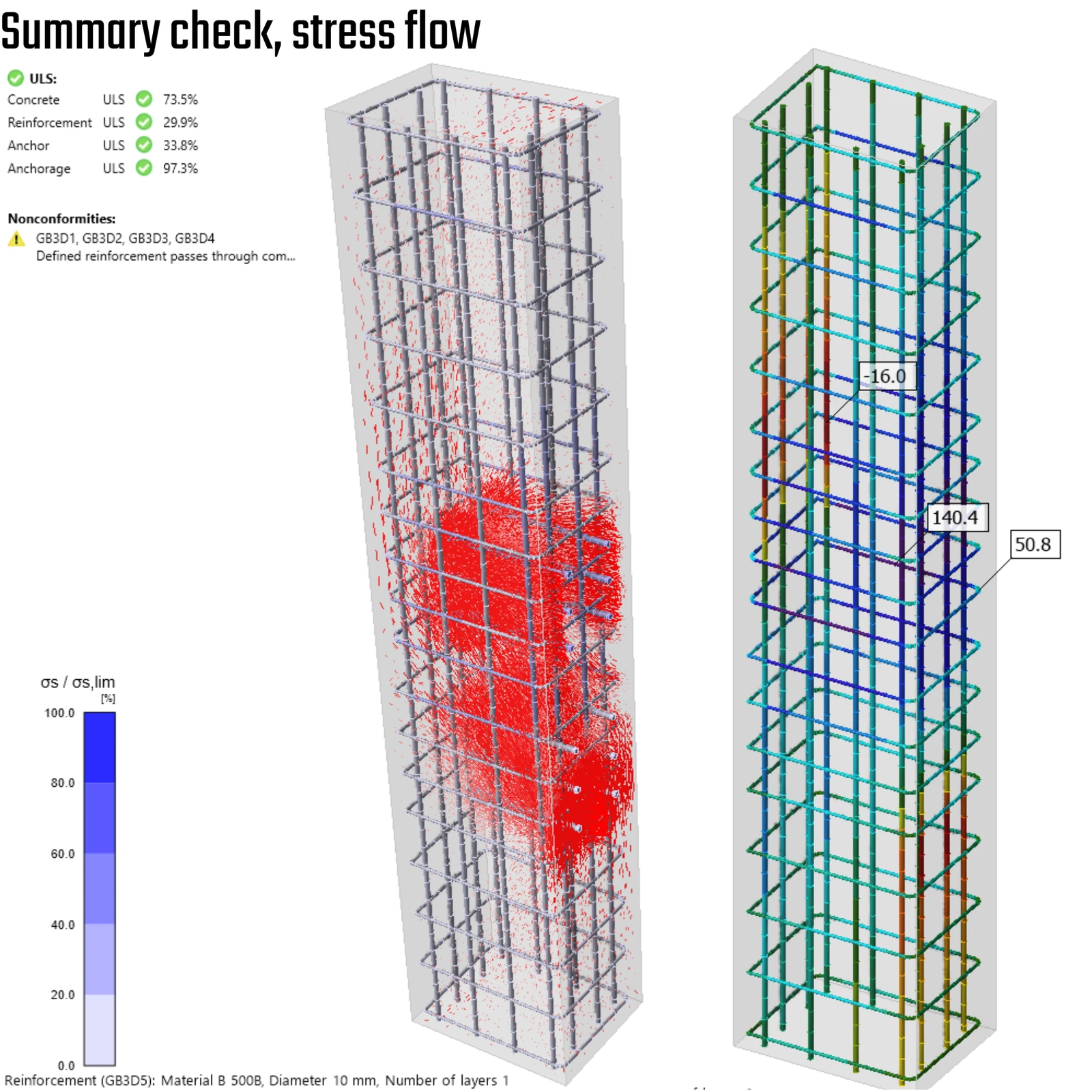
10) Summary check, stress flow
The deformed shape should be the first output, used to double-check the correctness of the boundary conditions. The deformed shape outlines the anticipated behavior.
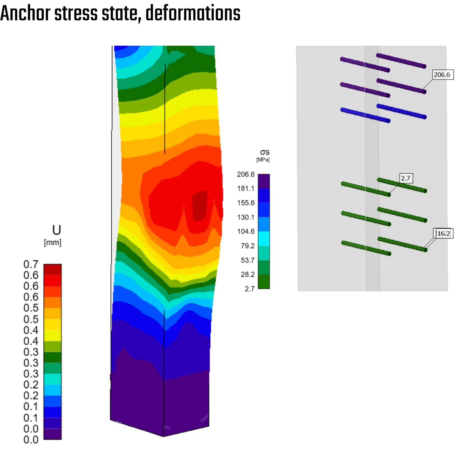
11) Anchors stress state, deformed shape
Conclusion and key takeaways
Truss model = axial idealization
Efficient for global force flow (tension/compression only), but bending and shear effects are suppressed and must be addressed at the connection level.
Centroidal assumption is critical
Misalignment between the bolt group and the section CG introduces secondary bending not captured in the global FEA. This must be verified in a detailed connection design.
Boundary conditions drive reality
For this case, the N–Vy–Vz constraint better reflects joint behavior. Rotational restraint and diagonal action significantly influence chord response.
Anchor checks in plain concrete are conservative
Simplified code assumptions may indicate failure. True capacity depends on reinforcement interaction and force redistribution in the concrete member.
Reinforcement closes the loop
The load path continues beyond the base plate. Only a 3D Detail (CSFM) model with reinforcement and realistic boundary conditions captures the composite behavior and prevents brittle failure modes.
Always check the deformed shape
If deformation matches structural intuition, the model likely reflects physical behavior.