Idea Statica
  • Steel
  • Concrete
  • BIM & Workflows
  • Support & Learning
  • Pricing
  • Company
  • Steel overview
  • Connection design
  • Member design
  • Parametric design
  • Steel case studies
  • Concrete overview
  • Walls and D-regions
  • Anchoring design
  • Concrete case studies
  • BIM Overview
  • Supported integrations
  • Checkbot
  • Viewer
  • APIs
  • Support Center
  • E-learning & certification
  • Blog
  • Downloads & Licensing
  • Plans
  • Free community tool
  • Enterprise customers
  • Students & educators
  • How much will you save?
  • About us
  • Contact
  • Research & development
  • Authorized resellers
  • Meet our customers
  • Career
  • Steel
    Steel overviewConnection designMember designParametric designSteel case studies
  • Concrete
    Concrete overviewWalls and D-regionsAnchoring designConcrete case studies
  • BIM & Workflows
    BIM OverviewSupported integrationsCheckbotViewerAPIs
  • Support & Learning
    Support CenterE-learning & certificationBlogDownloads & Licensing
  • Pricing
    PlansFree community toolEnterprise customersStudents & educatorsHow much will you save?
  • Company
    About usContactResearch & developmentAuthorized resellersMeet our customersCareer
14-Day Trial
14-Day Trial
  • Steel
  • Concrete
  • BIM & Workflows
  • Support & Learning
  • Pricing
  • Company

Subscribe to our newsletter

Company

  • About us
  • Partners
  • Careers
  • Patent

Resources

  • Customer projects
  • Case studies
  • Connection Library
  • Verification books

Legal

  • EULA
  • Privacy policy
  • California Privacy
  • TOS Viewer
  • Licensing

Help

  • Contact
  • Quote request
  • Resellers
  • Downloads
FacebookInstagramLinkedInYouTube

© IDEA StatiCa 2009-2026

Trusted and used worldwide by engineers, fabricators & consultants.

Support CenterKnowledge Base ArticlesGeneral description of Load impulses in Detail application
General description of Load impulses in Detail application
Loads in IDEA StatiCa Detail - Advanced Topics
Partially loaded areas
Internal forces and equilibrium in Detail application
What is the Topology optimization for? And how does it go with the strut and tie method?
Ordering of load cases and combinations in Detail
Auto-calculation of self-weight of discontinuity regions
Complete SLS combinations in Detail
Export Beam to Detail
Export of the beam to Detail app
General description of Load impulses in Detail application
ConcreteReinforced concreteKnowledge baseDetail 2DLoad effects

General description of Load impulses in Detail application

This article is also available in
ENCZDEESFRITPTNLHUROKRPLTHTRVIZH

In this article, you will learn about load impulses that can be set in the IDEA StatiCa Detail application. We will explain what are the options, and describe them individually. So, in the end, you shall be sure what is the difference between them and when and how to use them for your design.

Four types of load impulses can be defined for reinforced concrete discontinuity regions:

  • Point load
  • Line load
  • Surface load
  • Self-weight

Now, let's have a look at each of the options.

Point load

This simple load impulse is defined by its value, direction, inclination, position, and effective radius. The way how a point load is set can influence the method of how the load is applied to the model.

The first option is to set the load on edge. See the figure below.

The second option is to set the load generally into the model. The value of every applied load is calculated by weighted average where the weight is the distance from a point of application. In other words, the applied loads are variably distributed, not uniformly.

The third option is to adjust the load to the patch load - one of the load-transferring devices, by using the functionality in the Geometry section. 

The load application is shown in the image below.

Let's compare the images for the load placed into the model, and set using the patch load. Without patch load, the point load is applied to the elements of the concrete mesh. On the other hand, with patch load, the point load is applied straight to the reinforcement bars.

The patch load can be connected to the adjacent reinforcement automatically by the software. However, for that, you have to turn on the checkbox for the corresponding bars in the Reinforcement section.

In the figure below, you can see the case where the horizontal reinforcement was excluded from the patch load area, hence not considered for the load transmission.

The point loads can also be transferred via some other load-transmitting devices like bearing plates, hanging loads, and more. Do you want to know more about that? Read the article Support and load transmitting components.

The main principle is that point loads are applied to the model by elastic links with different stiffnesses. The stiffnesses are evaluated by weighted averages based on the length of the links. These links are connected to the points of the concrete or reinforcement mesh (where the blue arrows were drawn) and transfer the loads to the structure.

Line load

Line load can be defined as uniform or trapezoidal. The used type depends on the numerical load definition. When applying the linear line load, simply enter only one value to the corresponding cell in the data window. Nevertheless, if you need to specify the trapezoidal load, fill in values at one and the other end of the load. See the practical examples:

Example of a uniform load

Example of a trapezoidal load

The principle of applying the load is almost identical to the point load.

Surface load

The application of the surface load works the same way. It is applied to the nodes of the elements of the concrete structure's mesh.

Self-weight

The self-weight is a version of the surface load. The intensities are automatically calculated according to the selected cross-section.

Related articles

Supports in IDEA StatiCa Detail
  • Concrete
  • Detail 2D
  • Bridges
  • CSFM
  • Pier caps
  • +5
  • Concrete
  • Detail 2D
  • Bridges
  • CSFM
  • Pier caps

Knowledge base

Supports in IDEA StatiCa Detail - Advanced Topics

Read more
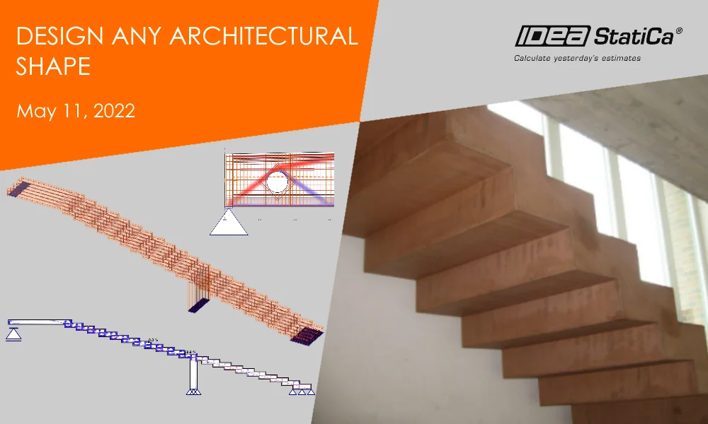
Design any architectural shape
  • Concrete
  • Detail 2D
  • EN (Eurocode)
  • Modeling
  • CSFM
  • DXF
  • Reinforcement
  • Cracks
  • +8
  • Concrete
  • Detail 2D
  • EN (Eurocode)
  • Modeling
  • CSFM
  • DXF
  • Reinforcement
  • Cracks

Webinar

Design any architectural shape

Read more
Loads in IDEA StatiCa Detail - Advanced Topics
  • Concrete
  • Detail 2D
  • ACI (USA)
  • Geometry
  • EN (Eurocode)
  • +5
  • Concrete
  • Detail 2D
  • ACI (USA)
  • Geometry
  • EN (Eurocode)

Knowledge base

Loads in IDEA StatiCa Detail - Advanced Topics

Read more