

General introduction to linear buckling analysis (LBA)
Buckling is a sudden sideways deformation caused by compressive forces, occurring well before material yield. Evaluating this instability requires modeling approaches distinct from standard stress-strain analysis (EPS), particularly regarding element length and boundary conditions.
Watch the recorded lecture on linear buckling analysis or read through the summary in the chapters below.
1) What is buckling
Buckling is the sudden sideways bending or deformation of a structural member (such as a column, beam, or strut) when it is subjected to compressive forces. It often occurs even though the material itself has not failed.
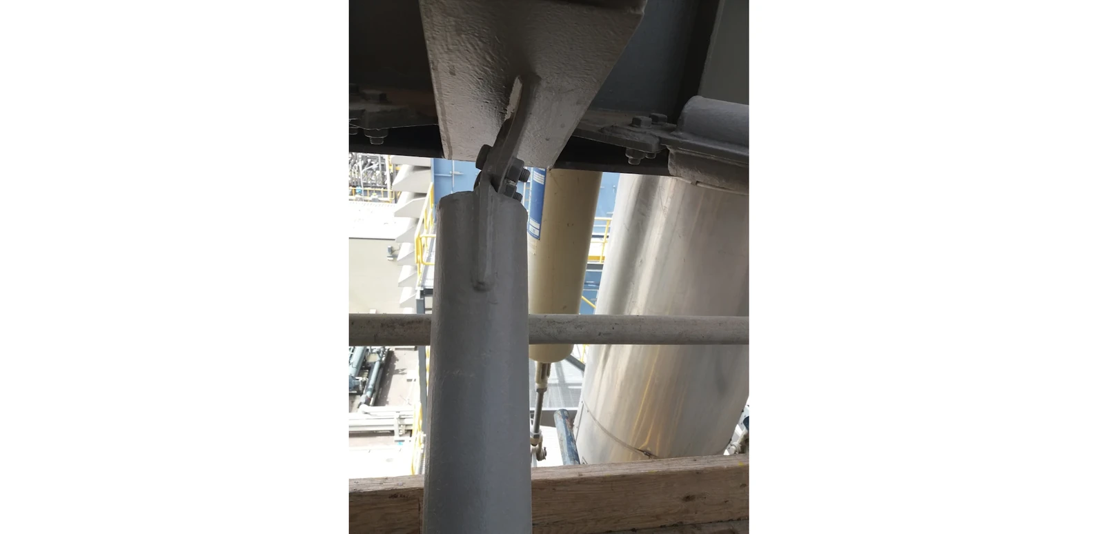
Key factors affecting buckling:
- Compressive load: Higher compression increases the risk.
- Length of the member: Longer members buckle more easily.
- Cross-sectional shape and size: Thicker or wider sections resist buckling better.
- Material properties: Stiffer materials are more resistant.
- Support conditions: How the member ends are fixed or supported affects the critical buckling load.
2) Governing equation
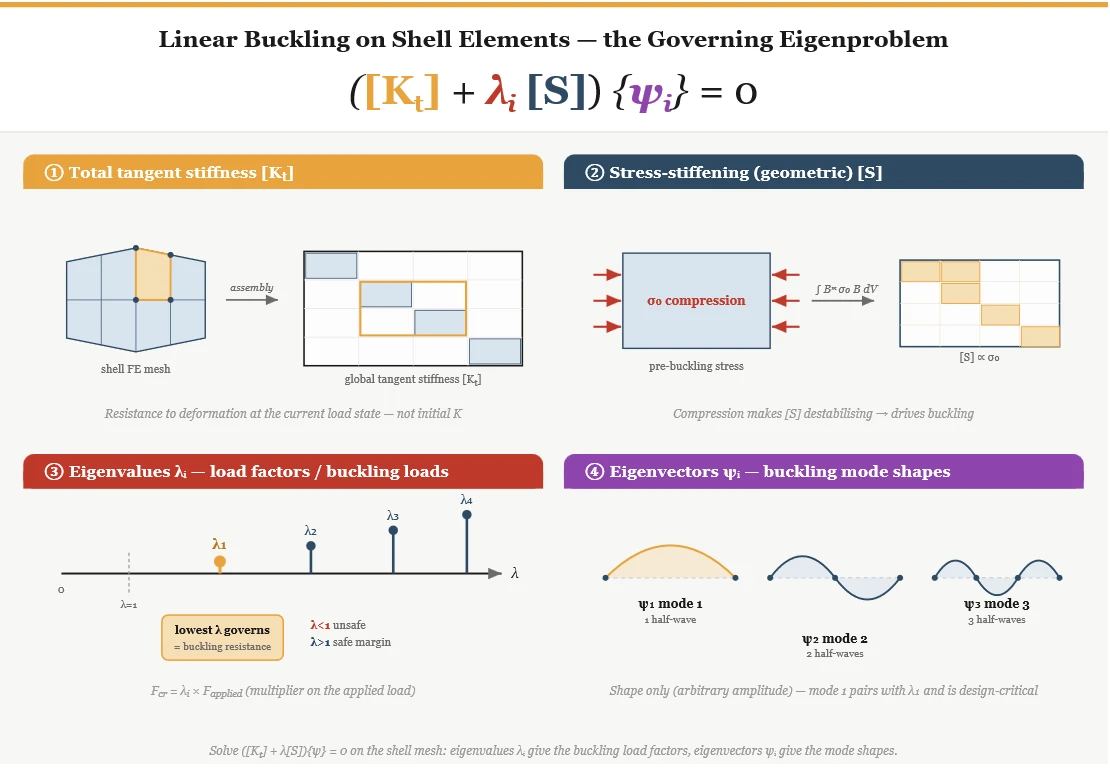
For the linear buckling analysis of shell elements, the governing eigenproblem is formulated as follows:
- Total tangent stiffness [Kt]: initial stiffness matrix in IDEA StatiCa.
- Stress stiffening matrix [S]: Positively tension/ negatively compression influences the lateral stiffness. In general, increase or decrease alpha_critical.
- Lambda (i): Eigenvalue, critical buckling factor.
- Phi (i): Eigenvector; determines the buckling shape for the i-th mode.
3) Linear buckling analysis (LBA) of a 1D compressed member
The computational workflow for evaluating structural instability through linear buckling analysis follows a systematic sequence:
- Model Initialization & Meshing: The structure's material properties and geometry are defined, and the model is discretized into finite beam or shell elements.
- Matrix Generation & Assembly: Element-level elastic stiffness (ke) and geometric stiffness (kg) matrices are computed and assembled into global matrices using the applied loads and boundary conditions.
- Eigenproblem Solution: The governing eigenvalue problem, (Ke-αKg)=0, is solved to extract the eigenvalues (α, representing buckling load factors) and eigenvectors (ψ, representing the corresponding buckling mode shapes).
- Critical Evaluation: The critical buckling load and governing mode shape are identified and visualized to assess structural vulnerability.
The identical methodology for model assembly is applied to the connection model, with the distinction that it is entirely developed using shell elements.
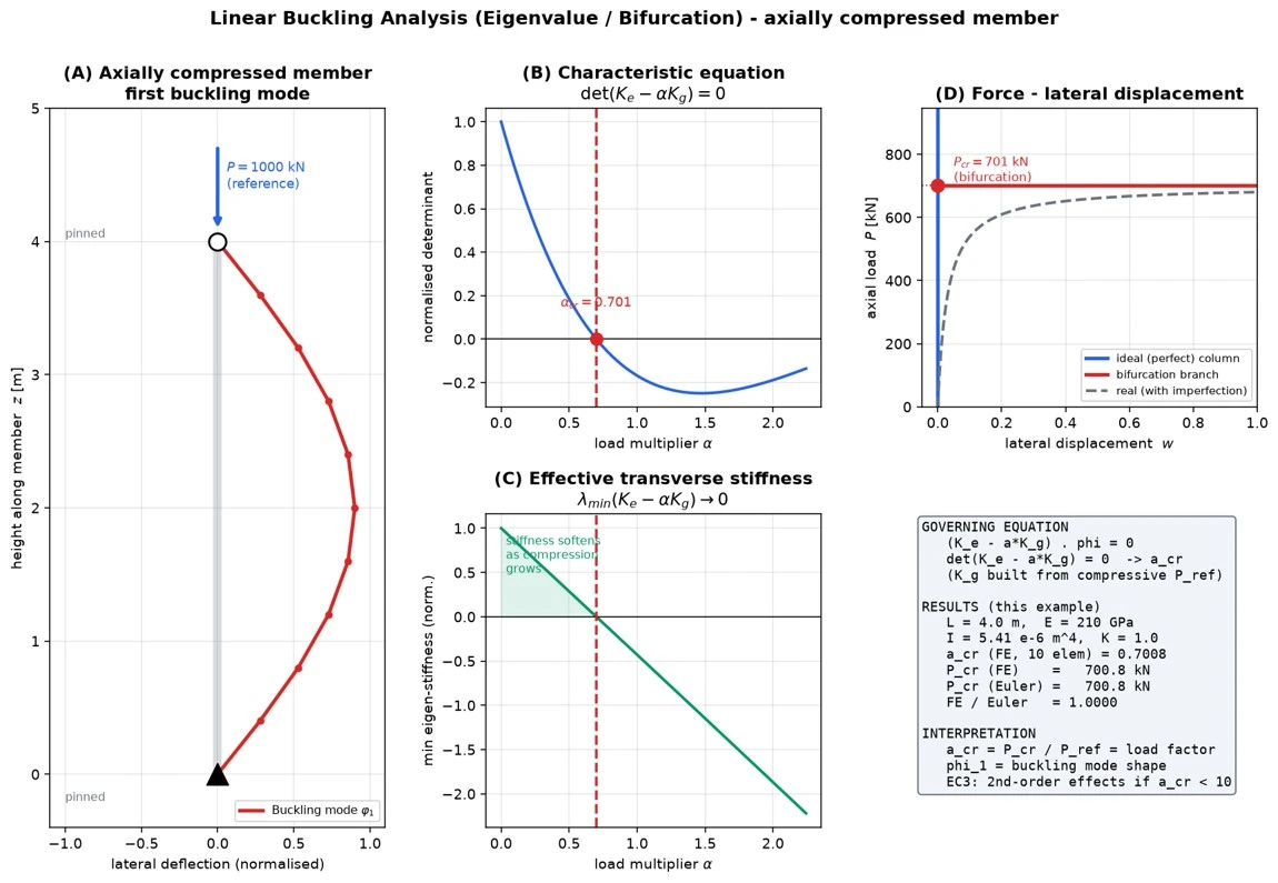
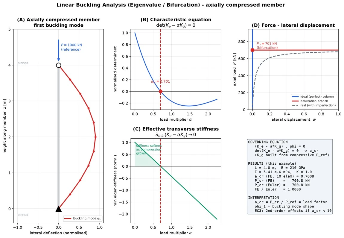
The graph below illustrates the eigenvalue (bifurcation) buckling behavior of an axially compressed structural member.
Buckling Analysis in IDEA StatiCa Connection
1) Setting the Model type for members
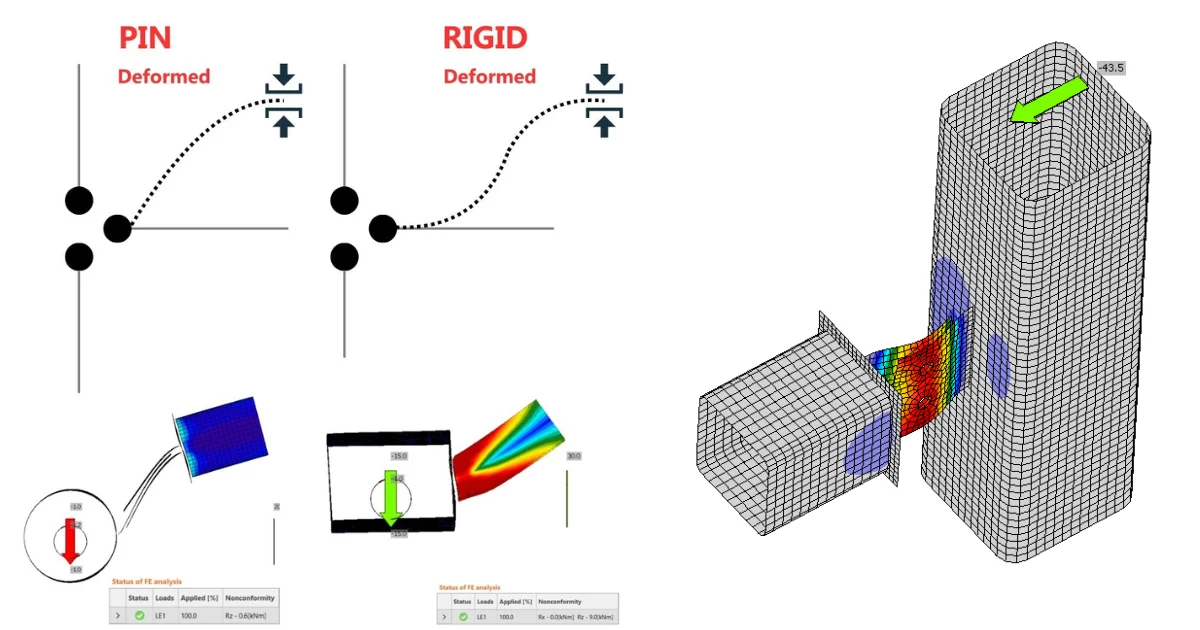
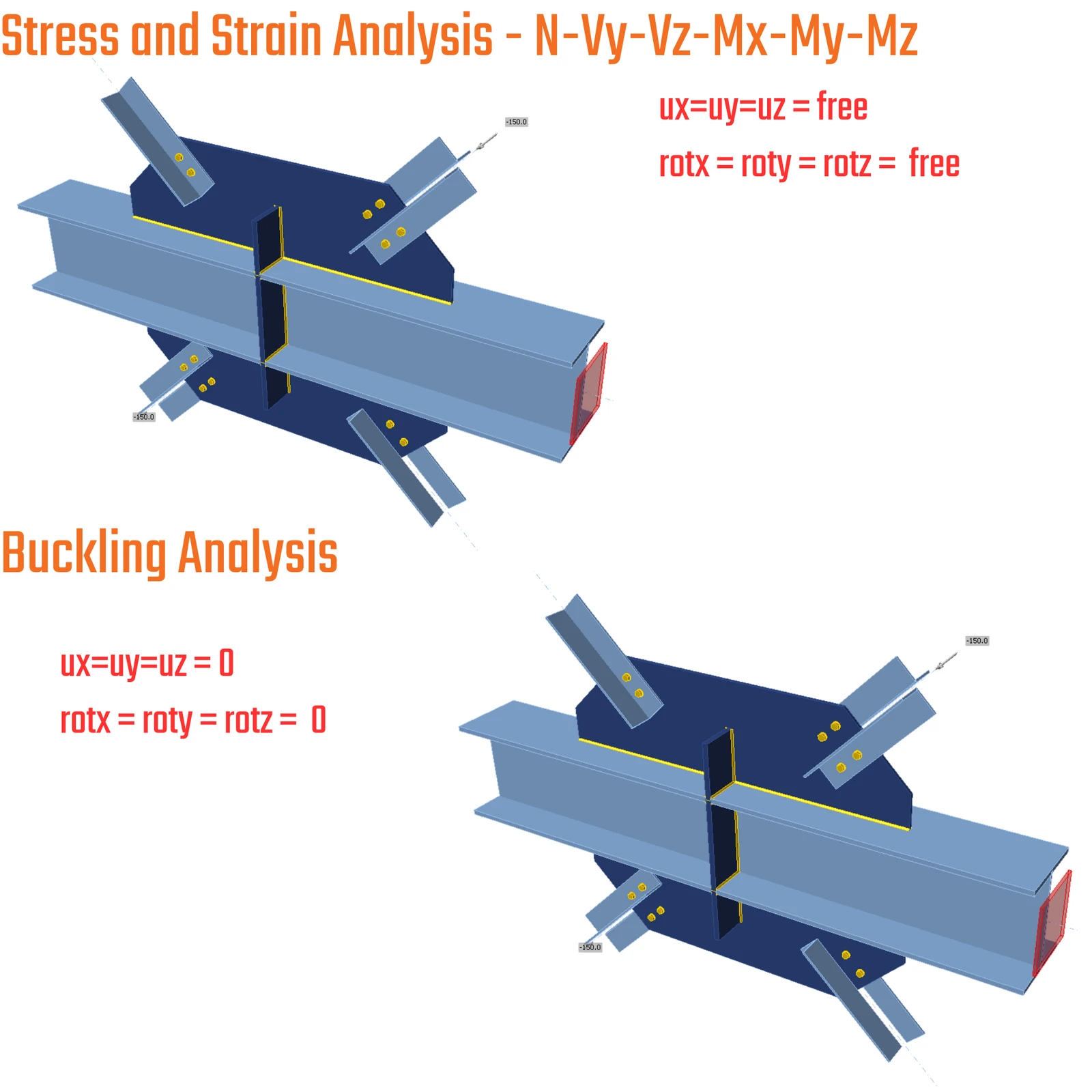
Model types play a critical role in structural simulations by directly controlling the resulting mode shapes. Below are the two most common and critical conditions used for structural connections and their comparison between the EPS analysis (standard material non-linear stress/strain analysis) and the Buckling analysis (LBA).
a) Model type N-Vy-Vz-Mx-My-Mz
EPS:
- The members with an assigned model type are unrestrained.
- The condensed element length is set to 4*h (four times the section height).
Buckling:
- All the members are locked at the end of the condensed element to prevent the unwanted member mode shapes.
- The condensed element length is set to 0.5*h (half the section height).
b) Model type N-Vy-Vz
EPS (N-Vy-Vz):
- Translations are free
- Rotations are restrained
Buckling:
- Translation in the local x - direction and all rotations are restrained
- Translation in the y and z directions is free to move
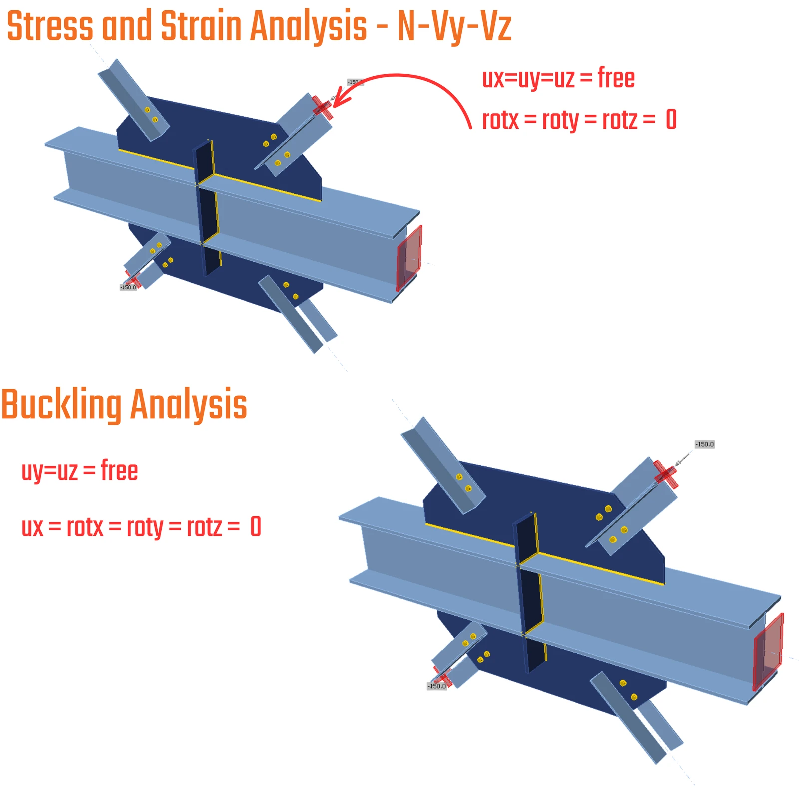
Model type - summary of settings for EPS vs Buckling analysis
- Model type N-Vy-Vz-Mx-My-Mz: supports in buckling model: N-Vy-Vz-Mx-My-Mz
- Model type N-Vy-Vz: supports in buckling model: N-Mx-My-Mz
- Model type N-Vz-My: supports in buckling model: N-Mx-My-Mz
- Model type N-Vy-Mz: supports in buckling model: N-Mx-My-Mz
References:
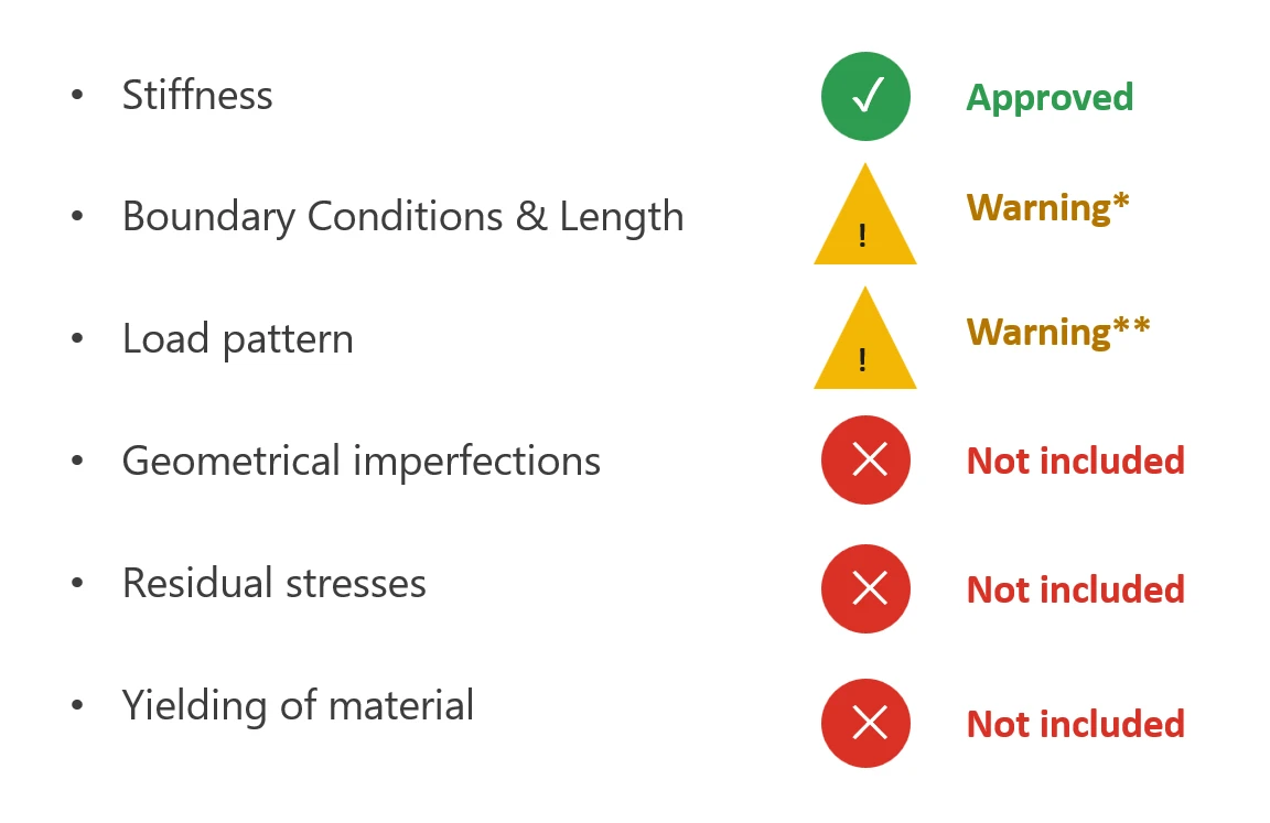
2) Limitations of Buckling Analysis in IDEA StatiCa Connection
- Stiffness — ✓ Included
Connection's shell FE model captures EI, GIt + EIw, and plate c/t stiffness directly from the actual plate/stiffener geometry you've modeled. For connection design: you don't need to estimate stiffness — the model already reflects your real plate thicknesses, stiffener layout, and section shape. - Boundary conditions & length — * Partially
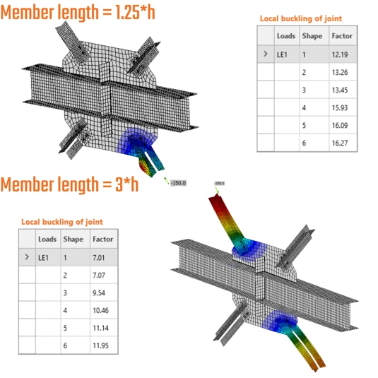
The length of the members is constrained by internal settings and implementation - hardcoded. It means that you are not able to specify precise member length and constraints at the end of the condensed element. It led to misleading assumptions about global buckling as a critical factor in alpha. For local buckling of plates inside the IDEA StatiCa Connection model, the solution introduces a safe and valid approach.
- Load pattern — ** Partially
The actual stress distribution from your applied loads (moment gradient, axial-bending interaction, load eccentricity) feeds directly into the eigenvalue analysis. For connection design: αcr reflects the actual combination of forces at that joint, not a simplified uniform-stress assumption. For global buckling phenomena, it is important to know whether the loads are causing a stabilizing or destabilizing effect, which is essentially dismissed in the IDEA StatiCa Connection model. This aspect negates the global buckling answer. - Geometrical imperfections — Excluded
Not applied as an initial bow/out-of-flatness inside the LBA run itself. For connection design: this is exactly why αcr is elastic-bifurcation, not real capacity — you still need to run it through a buckling curve (or GMNIA with a scaled imperfection shape) to get an honest resistance. - Residual stresses — Excluded
Also, not modeled directly; their effect is only picked up when you apply the code's buckling curve selection afterward. For connection design: don't expect αcr to already "know" that a welded stiffener sits on a worse curve than a rolled plate — that's on you to apply. In general, the buckling models do not account for this initial state due to residual stresses. Really complex pre-modeling process and thermal-stress analysis. - Yielding of material — Excluded
The LBA is purely elastic — fy never enters. For connection design, αcr indicates whether and where elastic bifurcation would occur in the joint components, not whether the material yields first. A low αcr flags a buckling-sensitive detail; it is not, by itself, the utilization check.
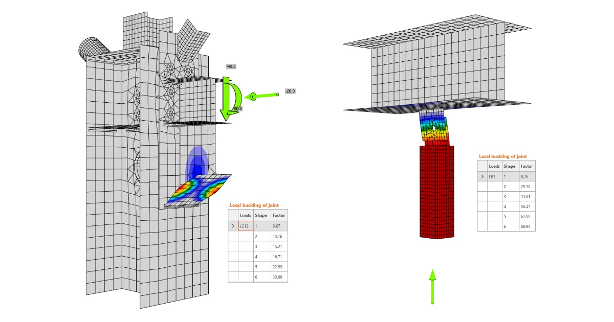
IDEA StatiCa Connection gives a relevant analysis output for the local buckling. For the global buckling analysis, it can be incorrect. Read more about local vs global buckling.
To correctly check the global buckling of a member or substructure, use the IDEA StatiCa Member app or another tool that takes into consideration the previously listed limitations.
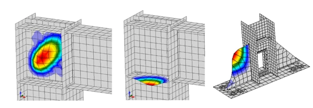
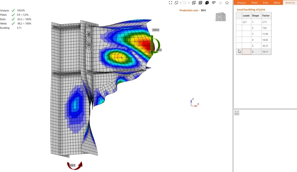
3) Local buckling analysis results evaluation
The structural parts (plates, etc.) under local buckling can be considered as safe (no further check needed) if the resulting critical factor αcr is greater than the safety thresholds, depending on the end supports.
Structural part is safe, if αcr:
- ≥ 2 - in case of a 4-sided supported plate
- ≥ 3 - in case of a 3-sided supported plate
- ≥ 4 - in case of a 2-sided (neighboring) supported plate
- ≥ 15 - in case of a 2-sided (opposite) supported plate
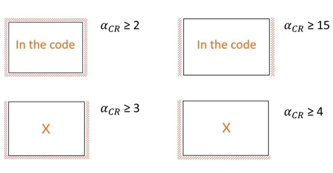
These safety thresholds are not applicable to Circular Hollow Sections (CHS), Rectangular Hollow Sections (RHS), and Class 4 cross-sections.
Conclusion and key takeaways
- Buckling is a stiffness problem, not a strength one. The critical factor follows from the tangent stiffness with the stress-stiffening matrix; compression lowers lateral stiffness and drives αcr down.
- EPS and Buckling are different models. LBA locks the member ends and shortens the condensed element to 0.5h (4h for EPS); the EPS stress state enters buckling as prestress.
- Only one of six critical factors is fully covered. Stiffness is included; geometrical imperfections, residual stress, and material yielding are not. Boundary Conditions and Load patterns are partially and insufficiently covered for the proper evaluation of Global Buckling.
- Boundary conditions and length are key limitations. The far end of the connected member is not represented, so the real buckling length is violated.
- Use it for local buckling of the connection only. Global member stability should be calculated in Member app.