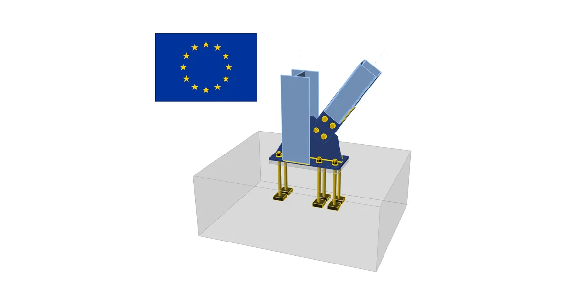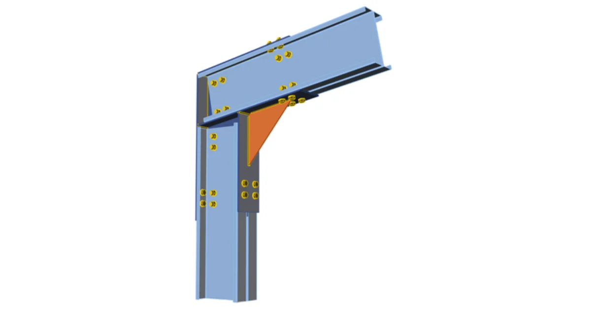


This can be achieved by creating new user-defined material based on the aluminium material properties in heat-affected zones (HAZ), applying the correct bilinear material model, and using bolt and weld checks according to 1993-1-8.
Aluminium is increasingly used in structural engineering thanks to its low weight, corrosion resistance, and long‑term durability. At the same time, aluminium behaves fundamentally differently from steel, especially in welded regions. The designer must account for HAZ softening, reduced ductility, and strong dependence of strength on alloy and temper.
IDEA StatiCa Connection can support aluminium design if specific behaviour is correctly represented in the model.
Material
Although aluminium has the same shape of material diagram, it requires additional user input because its mechanical properties are strongly affected by:
- alloy and temper,
- thickness,
- heat treatment history,
- welding and the resulting heat‑affected zone (HAZ).
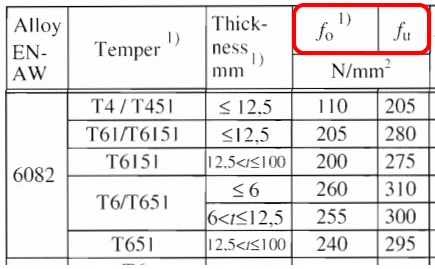
Proof stress (f₀) and ultimate tensile strength (fᵤ)
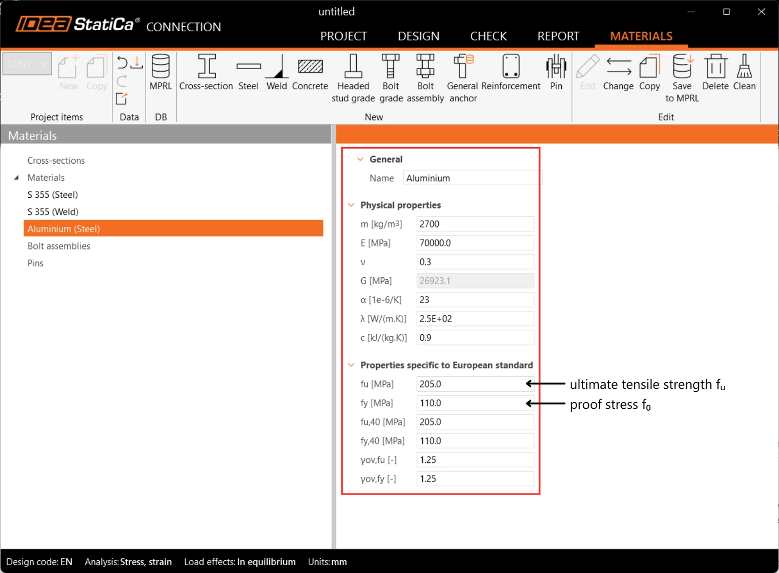
The proof stress (equivalent to the yield strength in steel) and the ultimate tensile strength vary for each alloy and temper. These values must be taken from EN 1999‑1‑1 and entered manually when defining a user material.
Heat‑affected zone (HAZ)
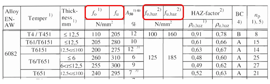
Welding reduces aluminium strength significantly, often by 40–60% in areas around welds called heat-affected zones. IDEA StatiCa does not automatically detect HAZ regions, so the user must specify them explicitly.
There are two options:
- Assign a separate material with reduced HAZ strengths to the relevant welded regions, or
- assign HAZ properties to the entire connection, which is conservative but practical and reflects the fact that most failures occur in or near the HAZ.
Material diagram
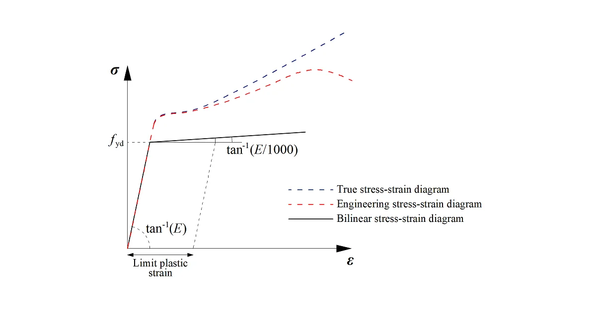
Aluminium exhibits significantly lower ductility than steel. For structural design in IDEA StatiCa, the following statements have been given:
- Because the plasticity of the aluminum alloy is highly dependent on the temper, the range of ultimate plasticity varies significantly across forming processes. We cannot provide a general statement about the limit plastic strain for all alloys.
- If the user wants to use plastic analysis, the limit of plastic strain for plates is at the user's discretion.
- The range of the ultimate limit engineering and fracture strains is shown below.
For typical structural aluminium alloys, the ultimate (uniform) engineering strain generally falls within the range of 4–10%, while the total fracture strain (elongation after rupture) is typically in the range of 9–18%, depending on alloy series and heat treatment.
Hardening modulus E₁
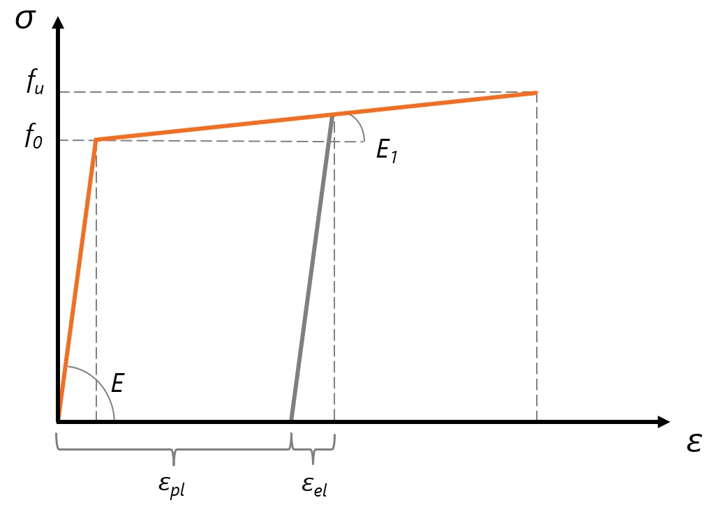
For aluminium, the hardening modulus E₁ is not constant and must be determined from fᵤ, f₀, εu, εp. This differs from steel, but IDEA StatiCa uses the fixed relation E₁ = E / 1000 and cannot be changed.
What does this mean in practice?
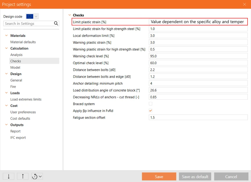
The limit plastic strain needs to be modified in Project settings.
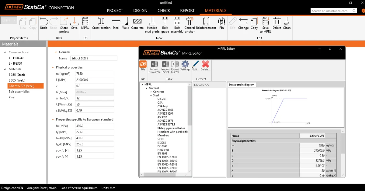
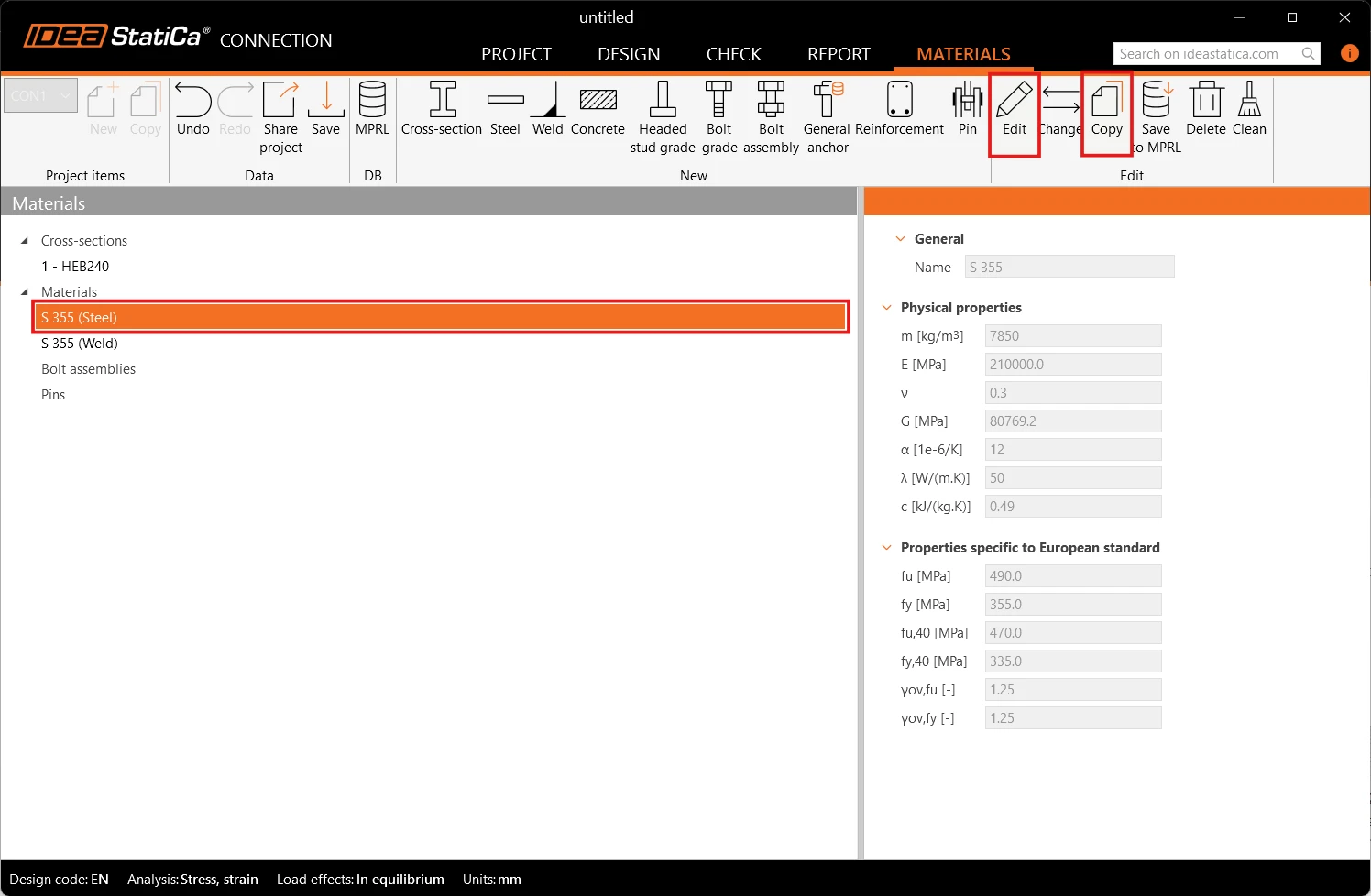
To create aluminium material, you need to go Materials tab, Copy existing material and Edit.
Then the material properties need to be adjusted according to aluminium specifics. If the connection includes welding, the HAZ values f0,haz and fu,haz must be addressed.
The user-defined materials can be saved in the MPRL library, where they are available to use in all future projects in IDEA StatiCa Connection.
Partial factors
For ULS check of materials, bolts, and welds are identical between codes – compatibility guaranteed.
Standard bolts
Most bolt checks in EN 1999‑1‑1 use the same equations and parameters as EN 1993‑1‑8. This means that:
- IDEA StatiCa’s existing bolt checks are fully applicable to aluminium connections.
- The only difference is the tension‑resistance factor k₂ for countersunk and aluminium bolts.
These types are not supported in IDEA StatiCa Connection, nor are rivets.

For standard steel bolts (the typical choice in aluminium structures), all checks remain valid.
Please note, that EN 1999 explicitly requires protection against galvanic corrosion when aluminium is in contact with other metals such as steel.
Preloaded (friction) bolts
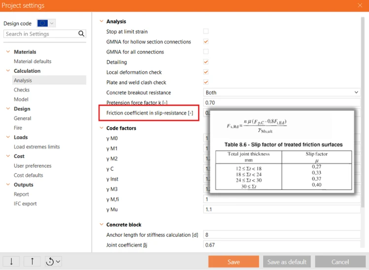
Friction coefficient for EN 1993-1-8 is based on the friction surfaces/treatment. The friction coefficient for EN 1999-1-1 is based on the thickness of friction surfaces.
In IDEA StatiCa, the friction coefficient μ can be set directly in Project settings, so values can be applied without limitation.
Welds
When welding is involved, the heat‑affected zone (HAZ) experiences a significant reduction in strength due to material degradation. These zones are not automatically recognised by the application, so users must represent them explicitly.
This can be done by:
- defining a separate HAZ material and assigning it to the affected part of the plate.
- conservatively applying HAZ properties to the entire connection, which avoids complex geometry modifications
The Von-Mises condition of plasticity is used as the failure criterion in IDEA StatiCa. It aligns with the assumption in EN 1993-1-8. The welds need to have an assigned material that corresponds to HAZ strength.
Conclusion
✅ Partial factors for materials, bolts, and welds are consistent between EN 1999‑1‑1 and EN 1993‑1‑8.
⚠️ Aluminium materials are not built in and must be defined by the user, including correct HAZ strengths.
⚠️ Plastic strain limit should be taken conservatively. The plastic strain for analysis is highly dependent on the temper and forming process.
❌ Hardening modulus E1 is dependent on fᵤ, f₀, εel, εmax for aluminium. IDEA StatiCa uses the fixed relation that cannot be changed. Low strain-hardening in IDEA StatiCa is conservative.
✅ Code-checks for standard and prestressed steel bolts are compatible with the current setup in IDEA StatiCa.
✅ Weld checks are compatible.
⚠️ HAZ zones must be defined explicitly, or the whole connection can conservatively use HAZ properties.
⚠️ The solution for aluminium connections has not been verified.
Note: A more detailed explanation of this topic is provided in the PDF document.