Idea Statica
  • Steel
  • Concrete
  • BIM & Workflows
  • Support & Learning
  • Pricing
  • Company
  • Steel overview
  • Connection design
  • Member design
  • Parametric design
  • Steel case studies
  • Concrete overview
  • Walls and D-regions
  • Anchoring design
  • Concrete case studies
  • BIM Overview
  • Supported integrations
  • Checkbot
  • Viewer
  • APIs
  • Support Center
  • E-learning & certification
  • Blog
  • Downloads & Licensing
  • Plans
  • Free community tool
  • Enterprise customers
  • Students & educators
  • How much will you save?
  • About us
  • Contact
  • Research & development
  • Authorized resellers
  • Meet our customers
  • Career
  • Steel
    Steel overviewConnection designMember designParametric designSteel case studies
  • Concrete
    Concrete overviewWalls and D-regionsAnchoring designConcrete case studies
  • BIM & Workflows
    BIM OverviewSupported integrationsCheckbotViewerAPIs
  • Support & Learning
    Support CenterE-learning & certificationBlogDownloads & Licensing
  • Pricing
    PlansFree community toolEnterprise customersStudents & educatorsHow much will you save?
  • Company
    About usContactResearch & developmentAuthorized resellersMeet our customersCareer
14-Day Trial
14-Day Trial
  • Steel
  • Concrete
  • BIM & Workflows
  • Support & Learning
  • Pricing
  • Company

Subscribe to our newsletter

Company

  • About us
  • Partners
  • Careers
  • Patent

Resources

  • Customer projects
  • Case studies
  • Connection Library
  • Verification books

Legal

  • EULA
  • Privacy policy
  • California Privacy
  • TOS Viewer
  • Licensing

Help

  • Contact
  • Quote request
  • Resellers
  • Downloads
FacebookInstagramLinkedInYouTube

© IDEA StatiCa 2009-2026

Trusted and used worldwide by engineers, fabricators & consultants.

Support CenterKnowledge Base ArticlesLoading and combinations
Modelling
Modeling options – Negative volume, Cutting plane and Cut, Related to Center Point
Loading and combinations
Modeling Grids and Self-weight
Load transferring devices
Reinforcement
Reinforcement Templates in Detail 3D
Import of anchoring from Connection to Detail
Single anchor definition
Anchoring plates options
Cast-in plates in Detail
Loading and combinations
ConcreteReinforced concreteKnowledge baseDetail 3DEN (Eurocode)

Loading and combinations

This article is also available in
ENCZDEESFRITPTNLHUROKRPLTHTRVIZH

Loading

Load cases can be defined in the same way as for 2D reinforced concrete elements. This means that each load case can be assigned either a Permanent or a Variable load type. The Permanent load cases are applied to the model first, and after a successful calculation, the Variable load cases are applied.

Type of load impulses

A total of 4 types of load pulses can be added to each load case.
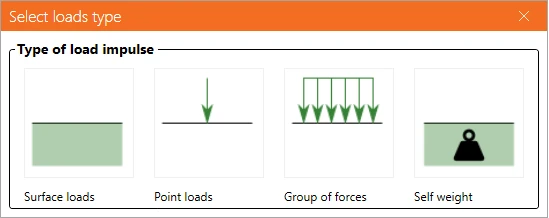
The definition of Surface loads is identical to the definition of Surface support. This means it is possible to specify it in two ways: Whole surface and Polyline. In the case of Surface loads, of course, the load intensity is entered in the three general directions.
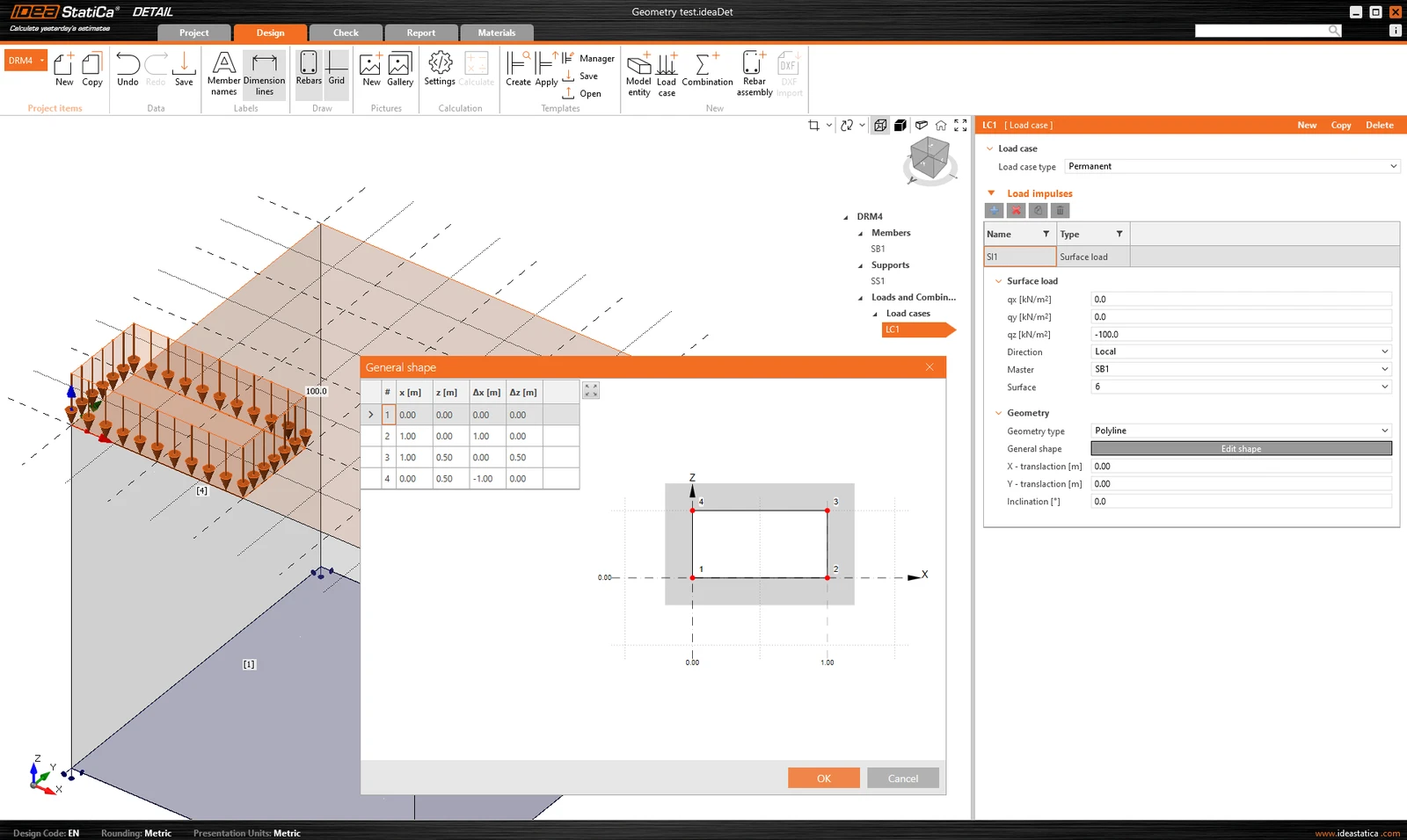
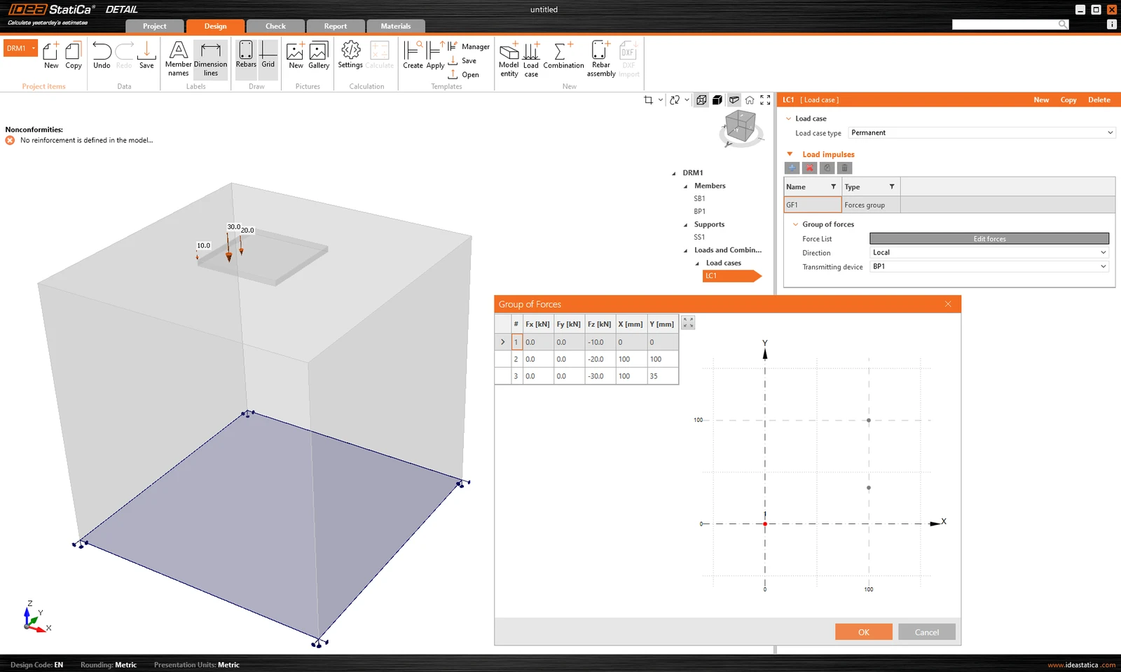
Group of forces is a load entity that allows you to specify forces in three directions anywhere on the model using a table. It can be referenced to the base plate or the surface of a concrete block. For tabular input, it is again possible to use the copy-paste functionality from the spreadsheet program.
The self-weight should be included in every model. For example, concrete foundations loaded with a bending moment will not so easily overturn.

Point loads can be loaded directly to the base plate with six internal forces Fx, Fy, Fz, Mx, My, and Mz in the general position. 
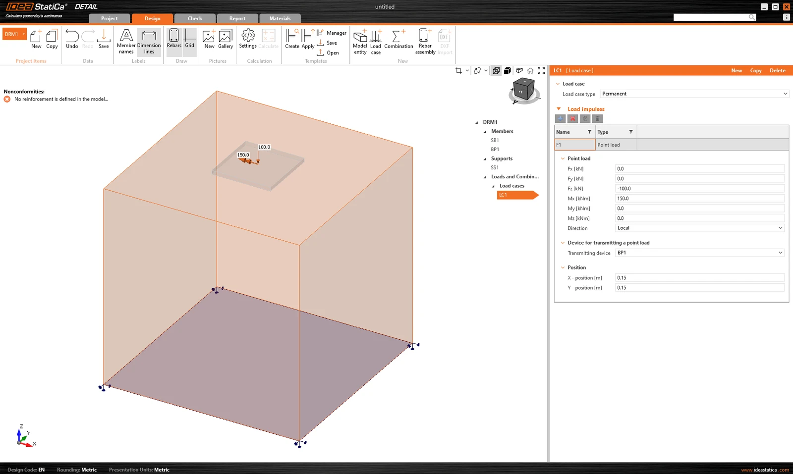
When using a base plate, applying this force directly to a realistic, deformable base plate can lead to unrealistic stress redistribution across the plate, anchors, and concrete. It is therefore more appropriate to use the second option - the stub.

The Stub

The stub is represented by a short part of the column above the base plate, which is modeled as a shell element structure and behaves as a physically accurate interface between the internal forces and the plate. A standard section database is used.
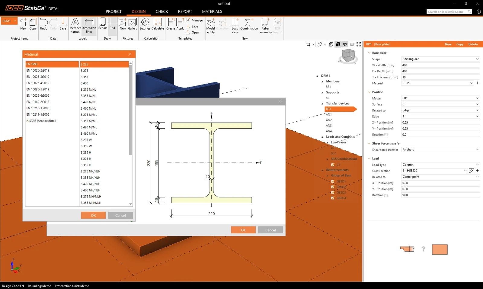
The 6-component internal force set (forces and moments) is applied at a single point on the bottom face of the stub - i.e. the base of the column.
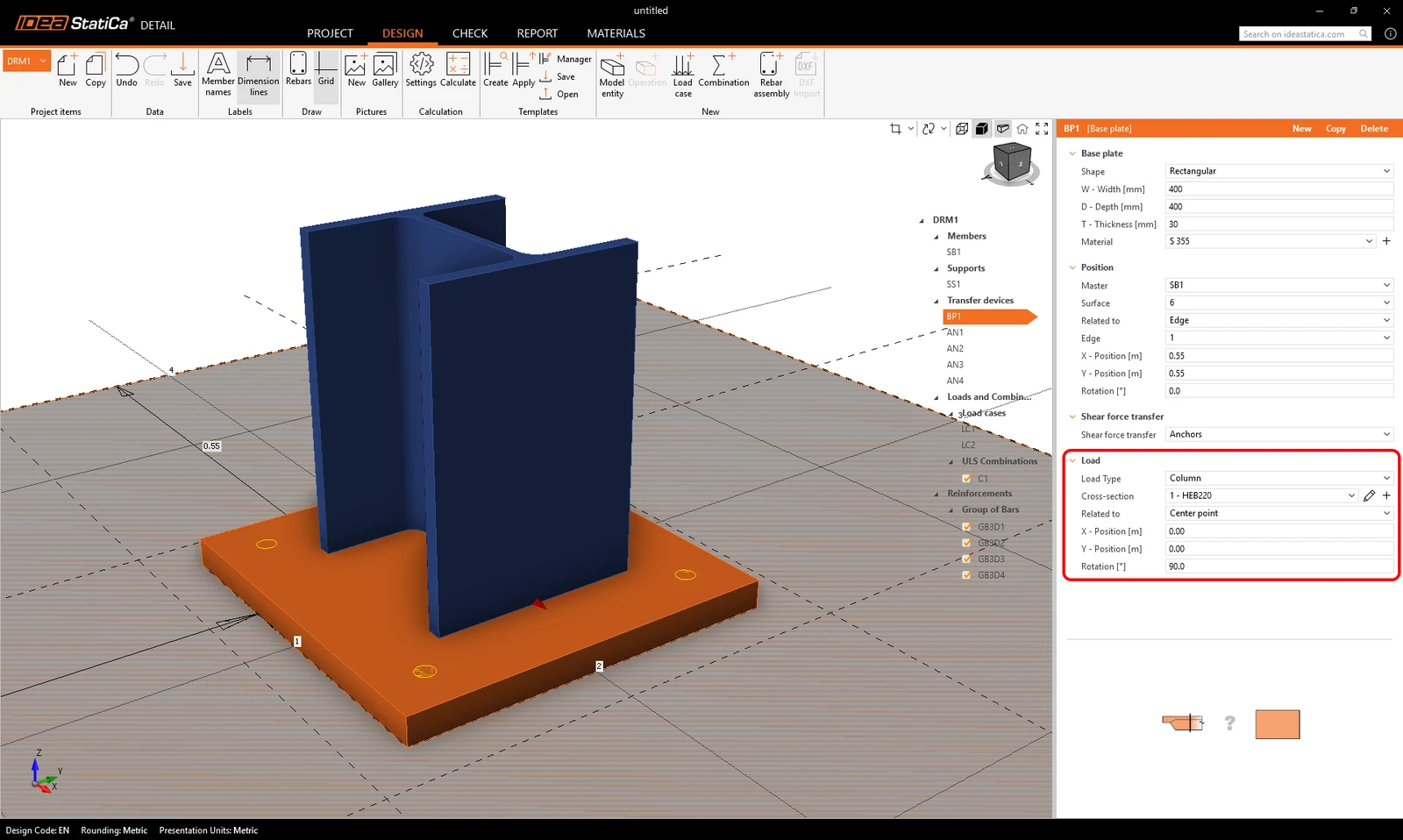
Constraints transfer the forces to the top face of the stub, from where they are naturally redistributed through the stub into the base plate, anchors, and concrete.
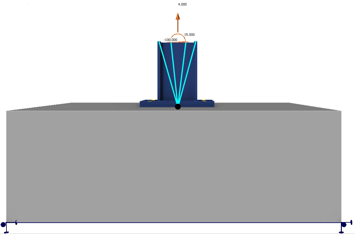
This approach preserves the realistic stiffness interaction between column and plate and eliminates the need for any manual redistribution or artificial assumptions.

The stub was released in IDEA StatiCa version 25.1.

Combinations

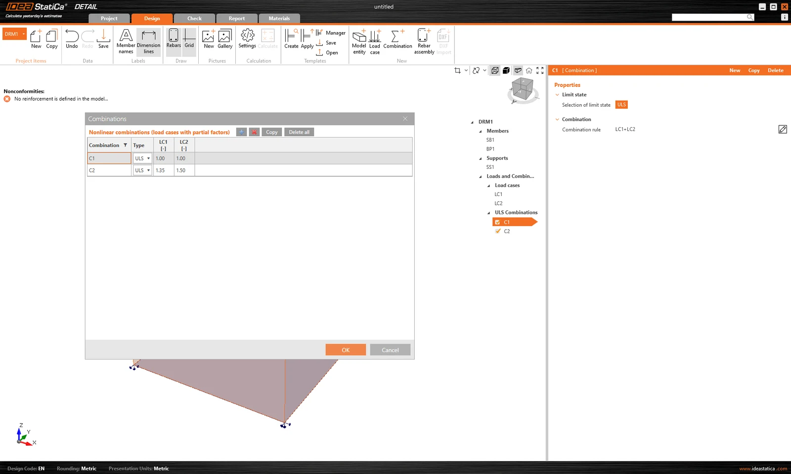
Because the analysis in IDEA StatiCa Detail is non-linear, so-called non-linear combinations are used. This means that individual load cases are not calculated and the results are not then added together. On the contrary, load cases of the same load type are added together before the calculation, of course with the respective coefficients defined in the combinations, and the individual combinations are then calculated. This is why the existence of at least one combination is a prerequisite for starting the calculation.

Only combinations for ULS can be defined.
Try out the new features of IDEA StatiCa today

Download the latest version for free

Related articles

IDEA StatiCa Detail is concrete design software for the structural design and code-check of concrete discontinuity regions in 3D space. Concrete members stress analysis & concrete wall design.
  • Concrete
  • EN (Eurocode)
  • CSFM
  • ULS
  • Geometry
  • Load effects
  • Overall check
  • Material settings
  • Limitations
  • Support
  • Corbels/Brackets
  • Reinforcement
  • Shear
  • Stress in reinforcement
  • Detail 3D
  • +15
  • Concrete
  • EN (Eurocode)
  • CSFM
  • ULS
  • Geometry
  • Load effects
  • Overall check
  • Material settings
  • Limitations
  • Support
  • Corbels/Brackets
  • Reinforcement
  • Shear
  • Stress in reinforcement
  • Detail 3D

Theoretical background

IDEA StatiCa Detail – Structural design of concrete 3D discontinuities

Read more
Known limitations for Detail 3D
  • Concrete
  • Detail 3D
  • EN (Eurocode)
  • ACI (USA)
  • Limitations
  • CSFM
  • +6
  • Concrete
  • Detail 3D
  • EN (Eurocode)
  • ACI (USA)
  • Limitations
  • CSFM

Knowledge base

Known limitations for Detail 3D

Read more
3D Detail tutorial - Eccentrically loaded anchoring
  • Concrete
  • Steel
  • Connection
  • EN (Eurocode)
  • CBFEM
  • CSFM
  • Detail 3D
  • +7
  • Concrete
  • Steel
  • Connection
  • EN (Eurocode)
  • CBFEM
  • CSFM
  • Detail 3D

Tutorials

Connection to Detail Integration: Eccentrically loaded anchoring (EN)

Read more
Complete code-check of anchors and concrete block with IDEA StatiCa (EN)
  • Concrete
  • Detail 3D
  • Anchoring
  • Connection
  • EN (Eurocode)
  • +5
  • Concrete
  • Detail 3D
  • Anchoring
  • Connection
  • EN (Eurocode)

Knowledge base

Complete code-check of anchors and concrete block with IDEA StatiCa (EN)

Read more