Idea Statica
  • Steel
  • Concrete
  • Support & Learning
  • Pricing
  • Company
  • Steel overview
  • Connection design
  • Member design
  • Parametric design
  • Steel case studies
  • Concrete overview
  • Walls and D-regions
  • Anchoring design
  • Concrete case studies
  • BIM Overview
  • Supported integrations
  • Checkbot
  • Viewer
  • APIs
  • Support Center
  • E-learning & certification
  • Blog
  • Downloads & Licensing
  • Plans
  • Free community tool
  • Enterprise customers
  • Students & educators
  • How much will you save?
  • About us
  • Contact
  • Research & development
  • Authorized resellers
  • Meet our customers
  • Career
  • Steel
    Steel overviewConnection designMember designParametric designSteel case studies
  • Concrete
    Concrete overviewWalls and D-regionsAnchoring designConcrete case studies
  • BIM OverviewSupported integrationsCheckbotViewerAPIs
  • Support & Learning
    Support CenterE-learning & certificationBlogDownloads & Licensing
  • Pricing
    PlansFree community toolEnterprise customersStudents & educatorsHow much will you save?
  • Company
    About usContactResearch & developmentAuthorized resellersMeet our customersCareer
14-Day Trial
14-Day Trial

Subscribe to our newsletter

Company

  • About us
  • Partners
  • Careers
  • Patent

Resources

  • Customer projects
  • Case studies
  • Connection Library
  • Verification books

Legal

  • EULA
  • Privacy policy
  • California Privacy
  • TOS Viewer
  • Licensing

Help

  • Contact
  • Quote request
  • Resellers
  • Downloads
FacebookInstagramLinkedInYouTube

© IDEA StatiCa 2009-2026

Trusted and used worldwide by engineers, fabricators & consultants.

Support CenterKnowledge Base ArticlesReinforcement
Modelling
Modeling options – Negative volume, Cutting plane and Cut, Related to Center Point
Loading and combinations
Modeling Grids and Self-weight
Load transferring devices
Reinforcement
Import of anchoring from Connection to Detail
Single anchor definition
Anchoring plates options
Cast-in plates in Detail
ConcreteReinforced concreteKnowledge baseDetail 3DEN (Eurocode)

Reinforcement

This article is also available in
ENCZDEESFRITPTNLHUROKRPLTHTRVIZH

The model can be reinforced with Group of bars 3D. This reinforcement type contains many options, which we will go through in the following text. Thus, 4 types of Definitions of bar shape can be specified:

  • By two points
  • On surface edge
  • On surface edge on more edges
  • On polyline

For each of these elements you can of course specify the diameter and material including the Anchorage type at the beginning and at the end of the bars.

Shape definition of the bar By two points is self-explanatory. You need to input two sets of cartesian coordinates X, Y, Z.
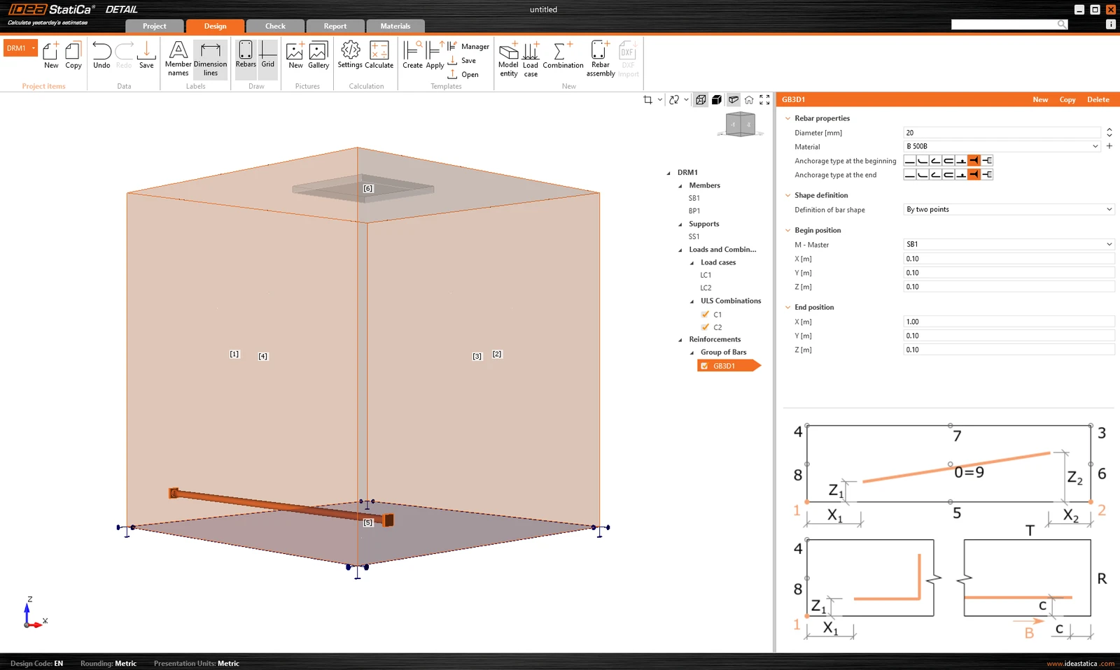
Definition On surface edge offers a lot of controls to position rebars to the required location. You can input reinforcement bars in more layers with more rebars in one layer with specified distances between bars in and between layers. Of course, it is also necessary to specify the reference surface and edge. Next, you must specify Surface cover, which defines the distance from the reference surface (from surface [1] in the figure below) and Edge cover, which defines the distance of the inserts from the side surfaces (from surfaces [4], [5], and [2] in the figure below), can be specified as From settings or User input. The default cover value (From settings) for the active Project item can be found in the first item of the tree (by default called DRM1) item of the tree. This was defined at the beginning of this article. The edge cover can be set as a unique value for each Group of bars.
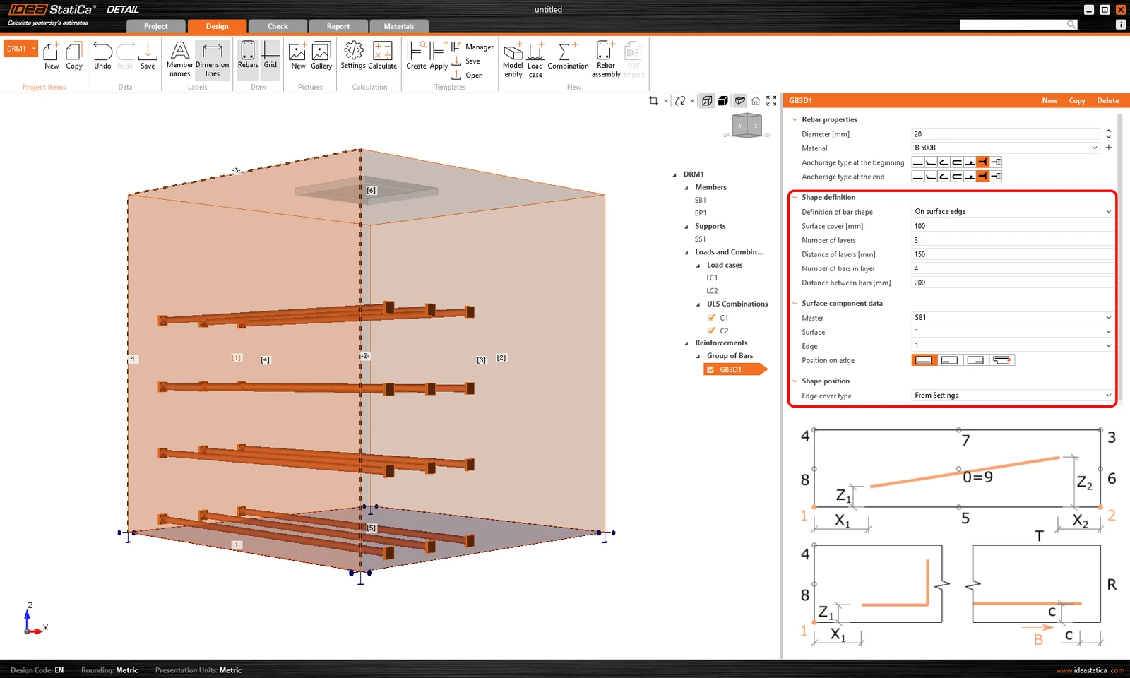
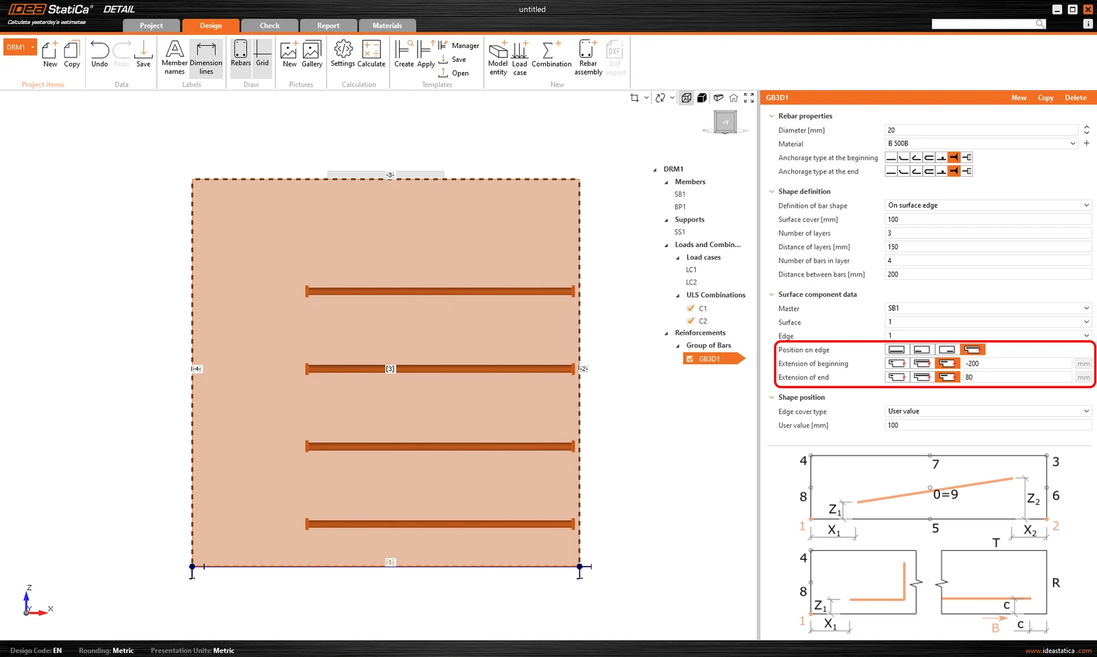
Lastly, Position on edge can be edited for this type of entry. For example, as shown in the figure below, it is possible to specify the reinforcement so that the User-defined Edge cover is applied only to the bottom surface [5]. The side surfaces are controlled by the Extension of the beginning and end.
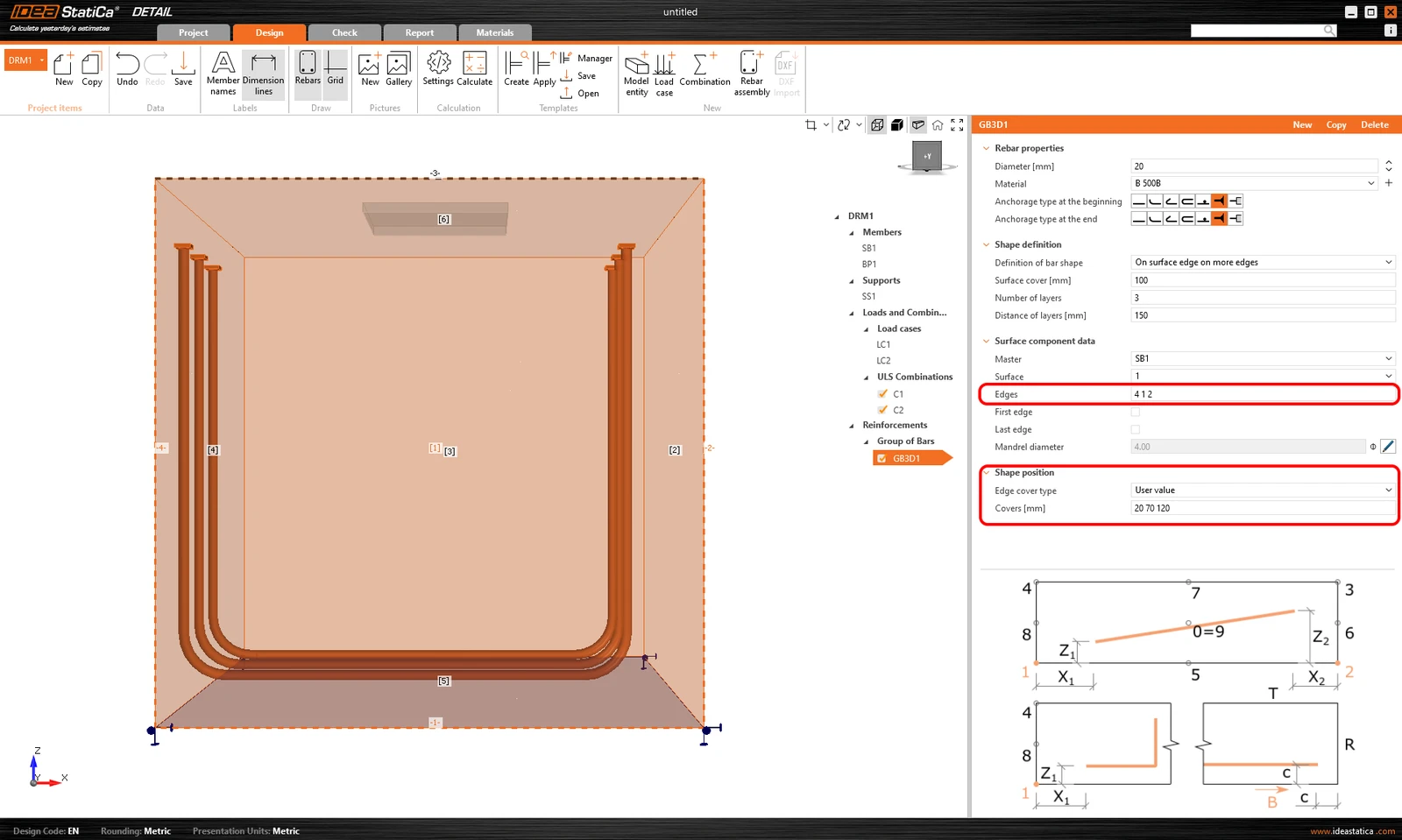
Another type of definition is On surface endge on more edges. Here it is possible to specify a list of edges or surfaces on which the reinforcement will be placed, together with a list of cover layers for each surface as shown in the following figure.
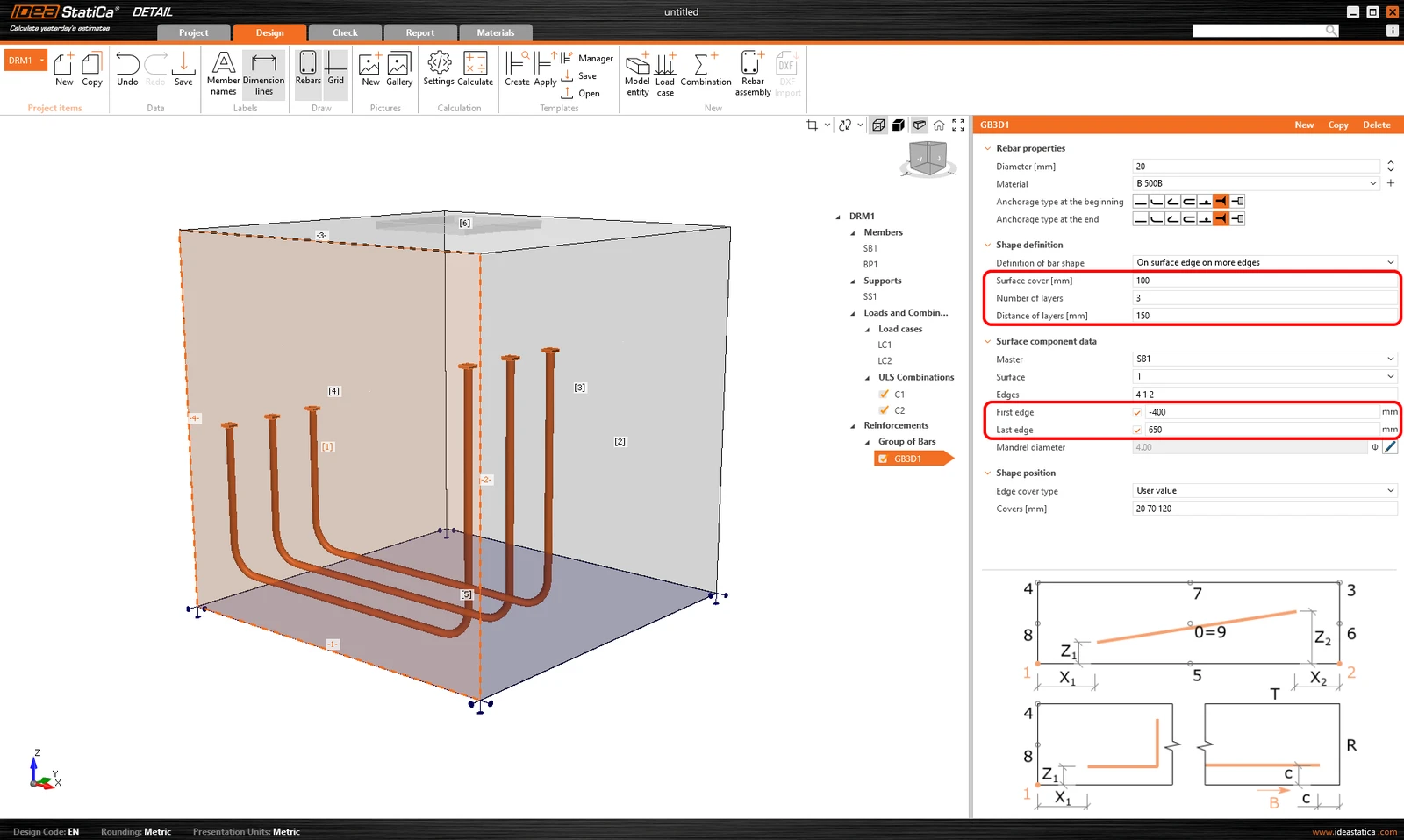
The cover can also be specified using the From settings option, as with the previous one. Again, it is possible to offset the reinforcement from the reference surface using the Surface cover and specify the Number and Distance of layers. It is also possible to lengthen or shorten the ends from the First edge and Last edge.
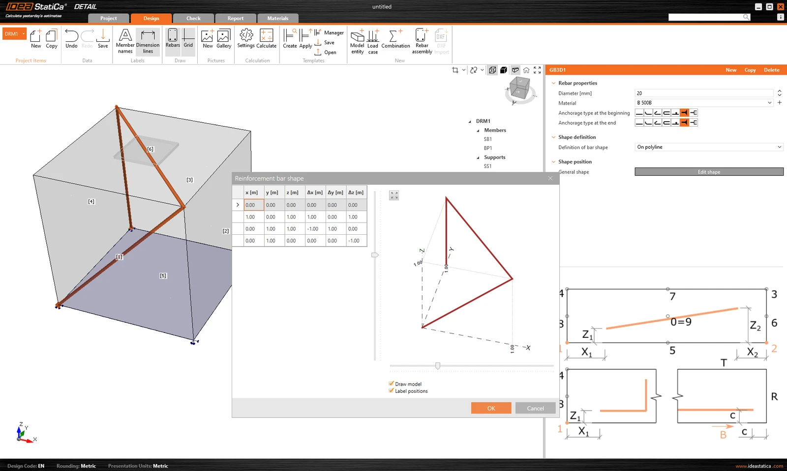
The last way of defining the reinforcement is On polyline. As in the model entities mentioned above, the reinforcement can be specified using a list of coordinates copied from a spreadsheet program. In this case, a 3D scene with the reinforcement displayed is additionally available for better orientation, allowing rotations around two axes.
Related articles

IDEA StatiCa Detail is concrete design software for the structural design and code-check of concrete discontinuity regions in 3D space. Concrete members stress analysis & concrete wall design.
  • Concrete
  • EN (Eurocode)
  • CSFM
  • ULS
  • Geometry
  • Load effects
  • Overall check
  • Material settings
  • Limitations
  • Support
  • Corbels/Brackets
  • Reinforcement
  • Shear
  • Stress in reinforcement
  • Detail 3D
  • +15
  • Concrete
  • EN (Eurocode)
  • CSFM
  • ULS
  • Geometry
  • Load effects
  • Overall check
  • Material settings
  • Limitations
  • Support
  • Corbels/Brackets
  • Reinforcement
  • Shear
  • Stress in reinforcement
  • Detail 3D

Theoretical background

IDEA StatiCa Detail – Structural design of concrete 3D discontinuities

Read more
Known limitations for Detail 3D
  • Concrete
  • Detail 3D
  • EN (Eurocode)
  • ACI (USA)
  • Limitations
  • CSFM
  • +6
  • Concrete
  • Detail 3D
  • EN (Eurocode)
  • ACI (USA)
  • Limitations
  • CSFM

Knowledge base

Known limitations for Detail 3D

Read more
3D Detail tutorial - Eccentrically loaded anchoring
  • Concrete
  • Steel
  • Connection
  • EN (Eurocode)
  • CBFEM
  • CSFM
  • Detail 3D
  • +7
  • Concrete
  • Steel
  • Connection
  • EN (Eurocode)
  • CBFEM
  • CSFM
  • Detail 3D

Tutorials

Connection to Detail Integration: Eccentrically loaded anchoring (EN)

Read more
Complete code-check of anchors and concrete block with IDEA StatiCa (EN)
  • Concrete
  • Detail 3D
  • Anchoring
  • Connection
  • EN (Eurocode)
  • +5
  • Concrete
  • Detail 3D
  • Anchoring
  • Connection
  • EN (Eurocode)

Knowledge base

Complete code-check of anchors and concrete block with IDEA StatiCa (EN)

Read more