
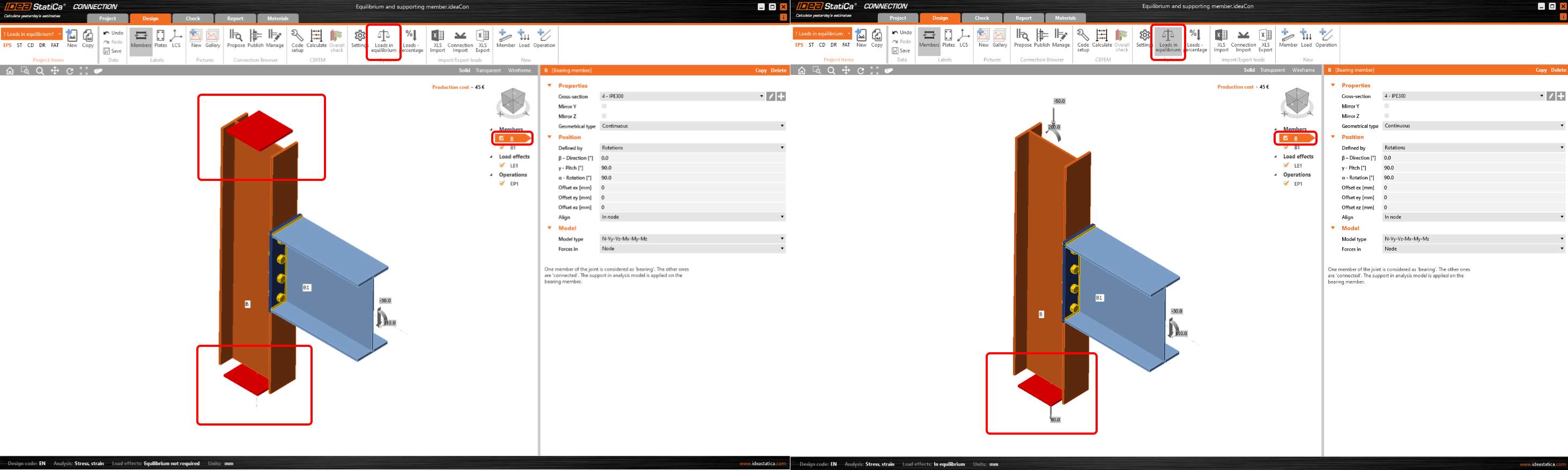
Bearing member and supports
One member of the joint is always set as "bearing". All other members are "connected". The bearing member can be chosen. The bearing member can be "continuous" or "ended" in the joint. "Ended" members are supported on one end, "continuous" members are supported on both ends. Supports are depicted as red squares at the continuous ends of the bearing member.
For more, read the articles Model types - additional boundary condition and Equilibrium and supporting member.
Defining the Model type
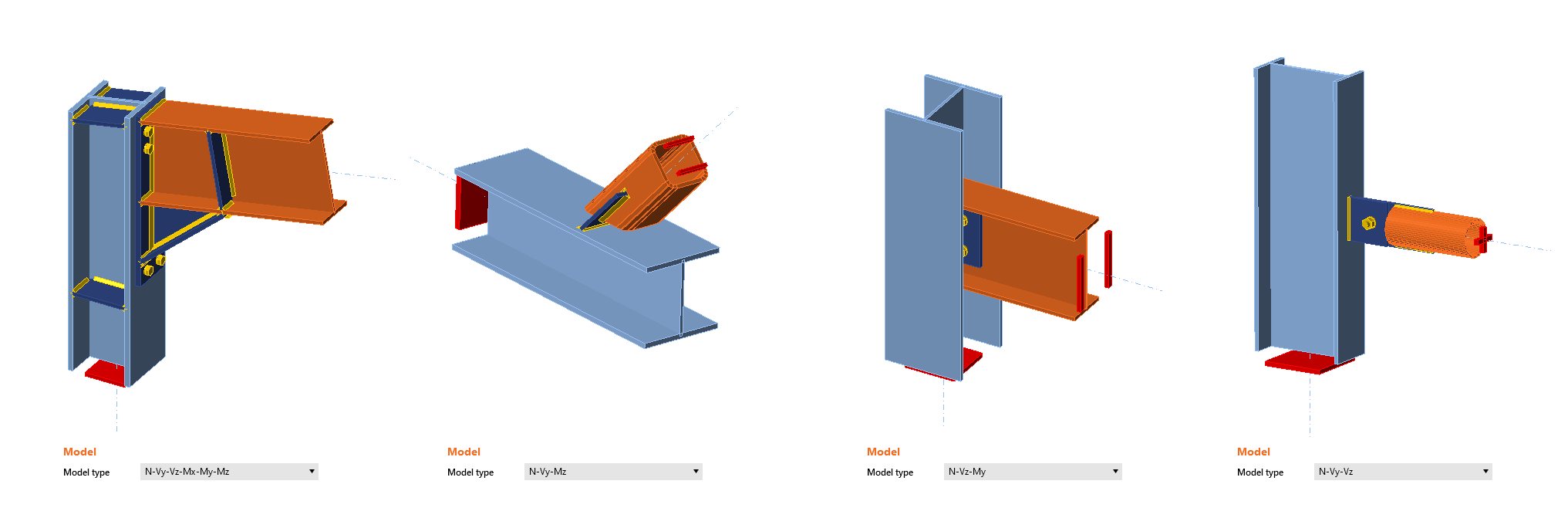
Connected members can be of several types, according to the load, which the member can take:
- Type N-Vy-Vz-Mx-My-Mz – member is able to transfer all 6 components of internal forces
- Type N-Vy-Mz – member is able to transfer only loading in XY plane – internal forces N, Vy, Mz
- Type N-Vz-My – member is able to transfer only loading in XZ plane – internal forces N, Vz, My
- Type N-Vy-Vz – member is able to transfer only normal force N and shear forces Vy and Vz
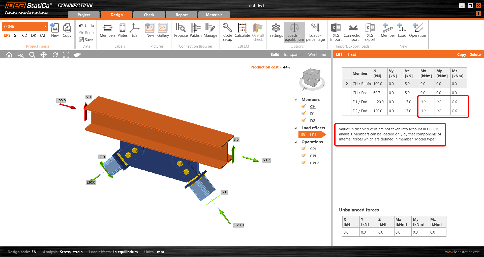
Appropriate support types respecting the type of the individual members should be defined at the ends of the connected members to prevent the occurrence of unstable mechanisms or unrealistic deformations.
Based on the selected model type, the corresponding cells in the load table are "locked" (prevented from defining).
One bolt connection
Sometimes, the engineer needs to make a joint with one bolt only, especially if e.g. a hinge, a bracing, a rod, or a diagonal is expected. To model and calculate this kind of operation, you need to define a proper Model type of the member.
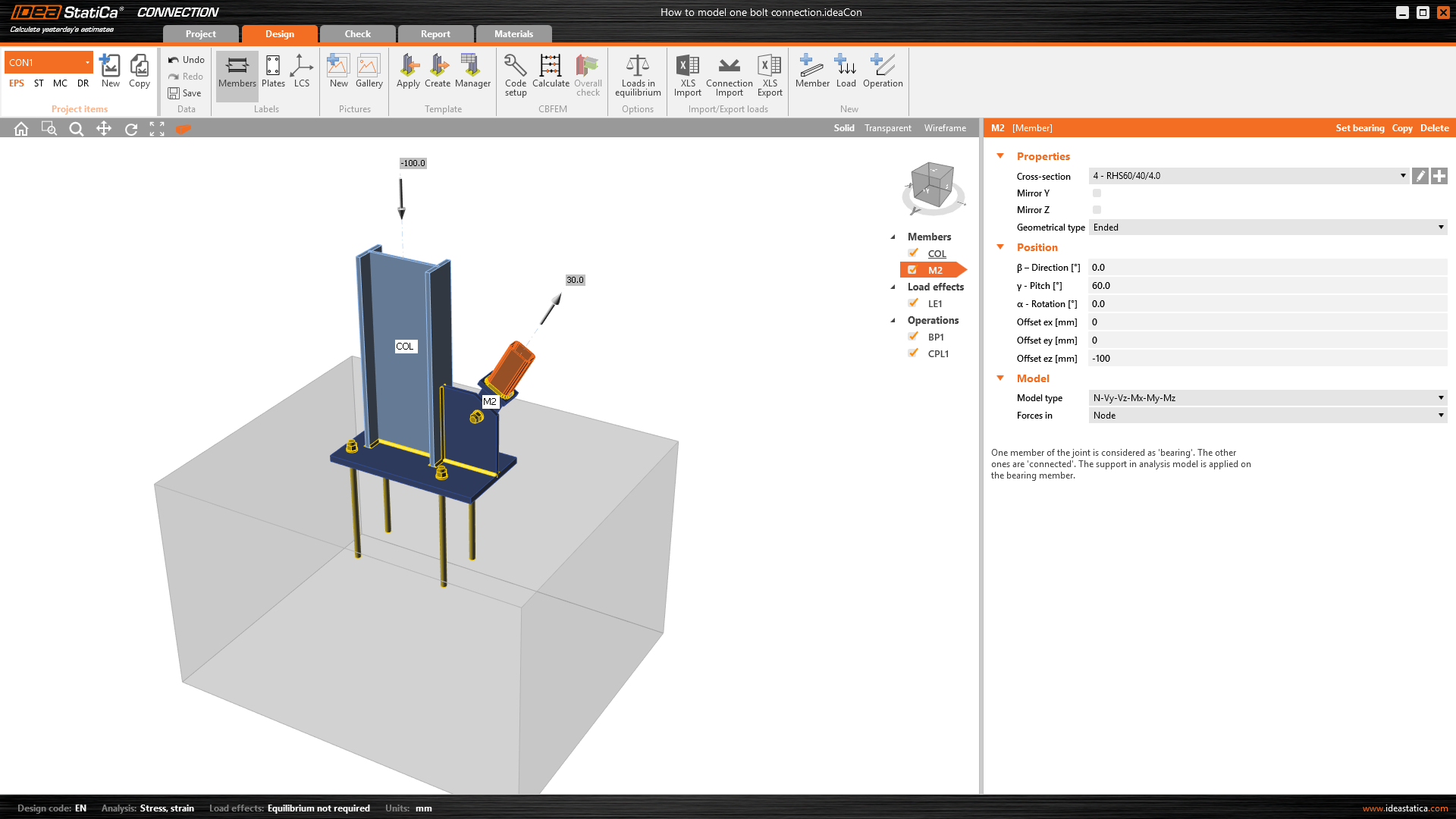
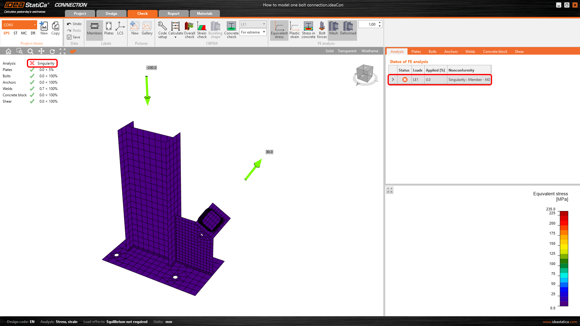
If you use the standard Model type: N-Vy-Vz-Mx-My-Mz for a member connected only with a single bolt, the mechanism/singularity can occur or the analysis fails.
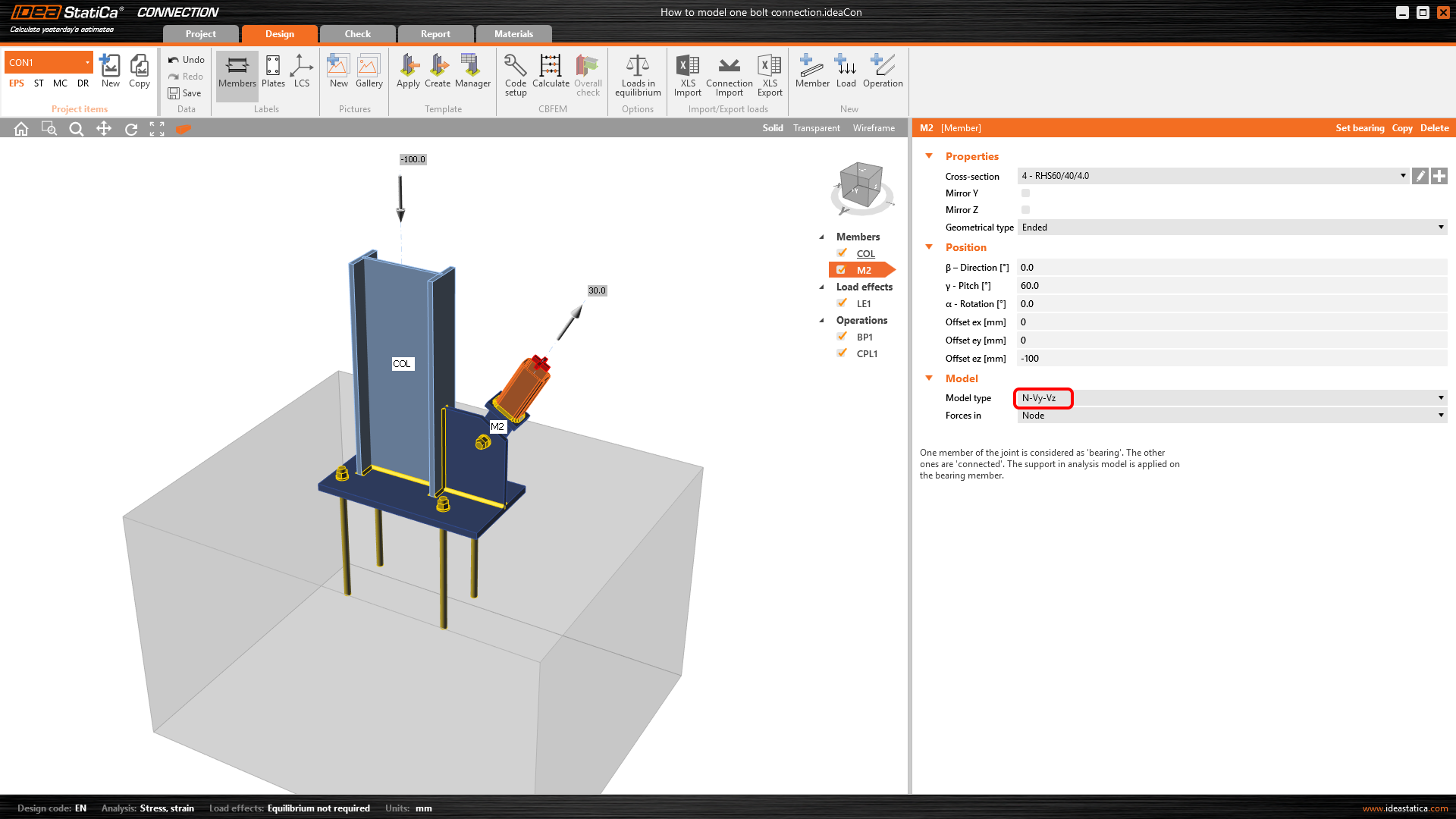
You have to change the Model type to N-Vy-Vz in the Properties of the hinge-connected member.
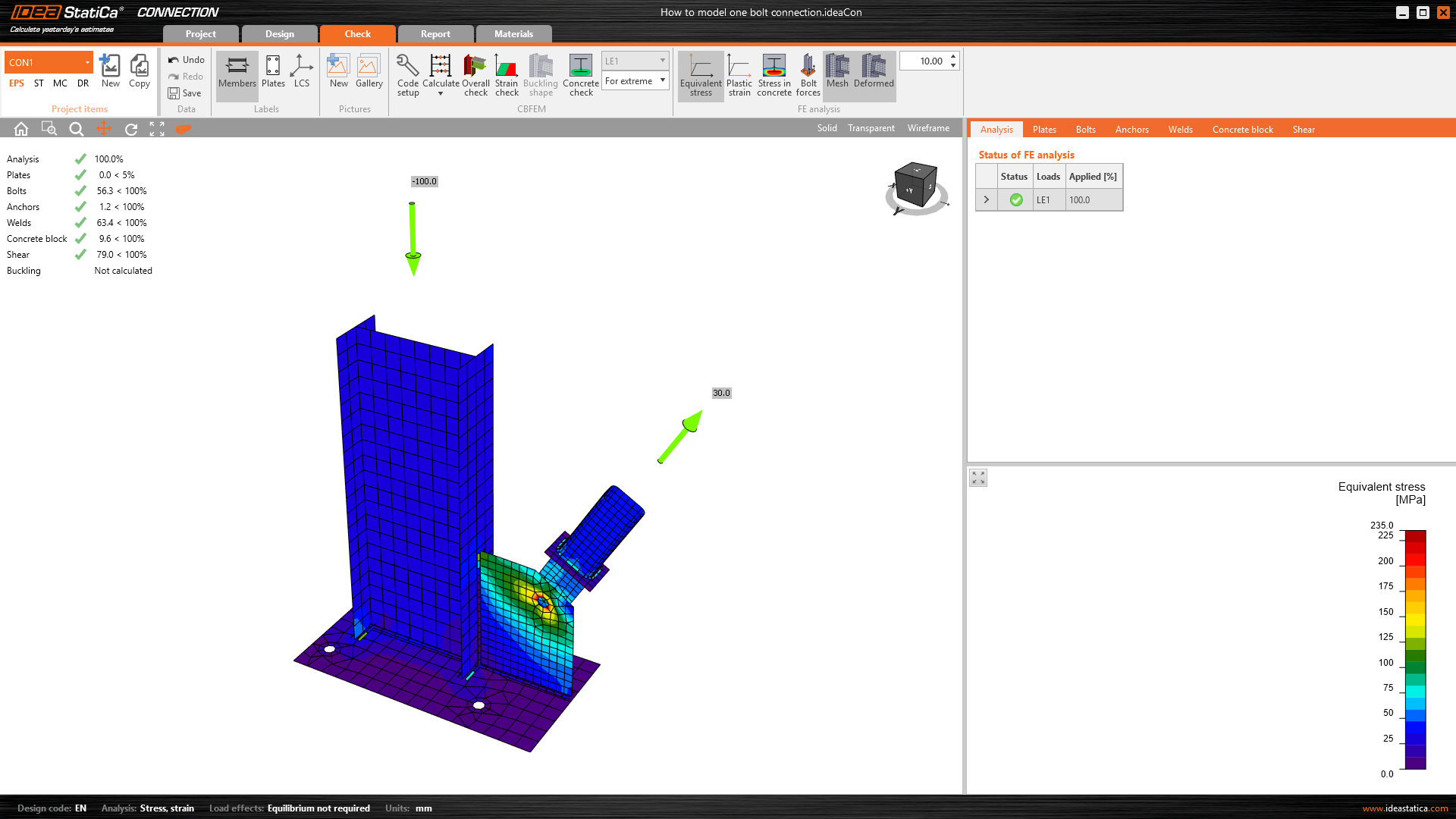
Now, the model is correct and the mechanism is prevented.
Webinar recording
See the recording of our webinar where setting the model type, and one bolt connection is demonstrated live.