Idea Statica
Steel
Concrete
BIM & Workflows
Support & Learning
Pricing
Company
14-Day Trial
Support CenterKnowledge BaseHow to merge the joint from CAD and FEA software
IDEA StatiCa BIM interoperability for steel
IDEA StatiCa BIM interoperability for concrete
Checkbot – bulk BIM workflows
Bulk workflows and critical load filter in Checkbot
Export of editable connections from Checkbot
How to merge the joint from CAD and FEA software
Add or merge nodes of connections and members in Checkbot
Import of recommended welds
Checkbot ready for big projects
Checkbot Free – the structural design hub for FEA and CAD data
Checkbot (BIM link) does not start
How to merge the joint from CAD and FEA software
SteelConnection designKnowledge baseConnectionCheckbot

How to merge the joint from CAD and FEA software

This article is also available in
ENCSDEESFRITPTNLHURO

In typical engineering practice, the FEM project is often developed alongside the CAD project. These two can be integrated for overall design and code-checks. The loads from the FEA analysis can be seamlessly transferred into the CAD model.

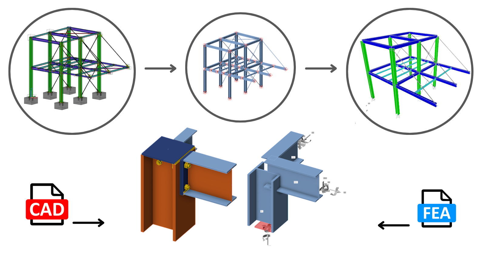
This feature is available for all supported FEM/CAD software. Importantly, the link between the two project files is maintained, allowing for easy updates and modifications.

Will the merge work for slightly different geometries? Typically, the analysis model differs from the drawing model. No, it will not. The geometry must be identical. The analytical model should closely represent reality, accounting for factors such as eccentricities and other variations.

In the background, an algorithm compares the positions of members in both projects. This means you don't need to worry about the order of the members; only the bearing member should match.

If the topology of the connections you want to merge differs (e.g., a different number of members or variations in member rotation), the software will issue a warning, and nothing will be imported. Additionally, the "Loads in Equilibrium" option (ensuring unbalanced forces = 0) serves as a verification tool for you.

Standard procedure for merging two separate files (CAD and FEA) together: 

STEP 1

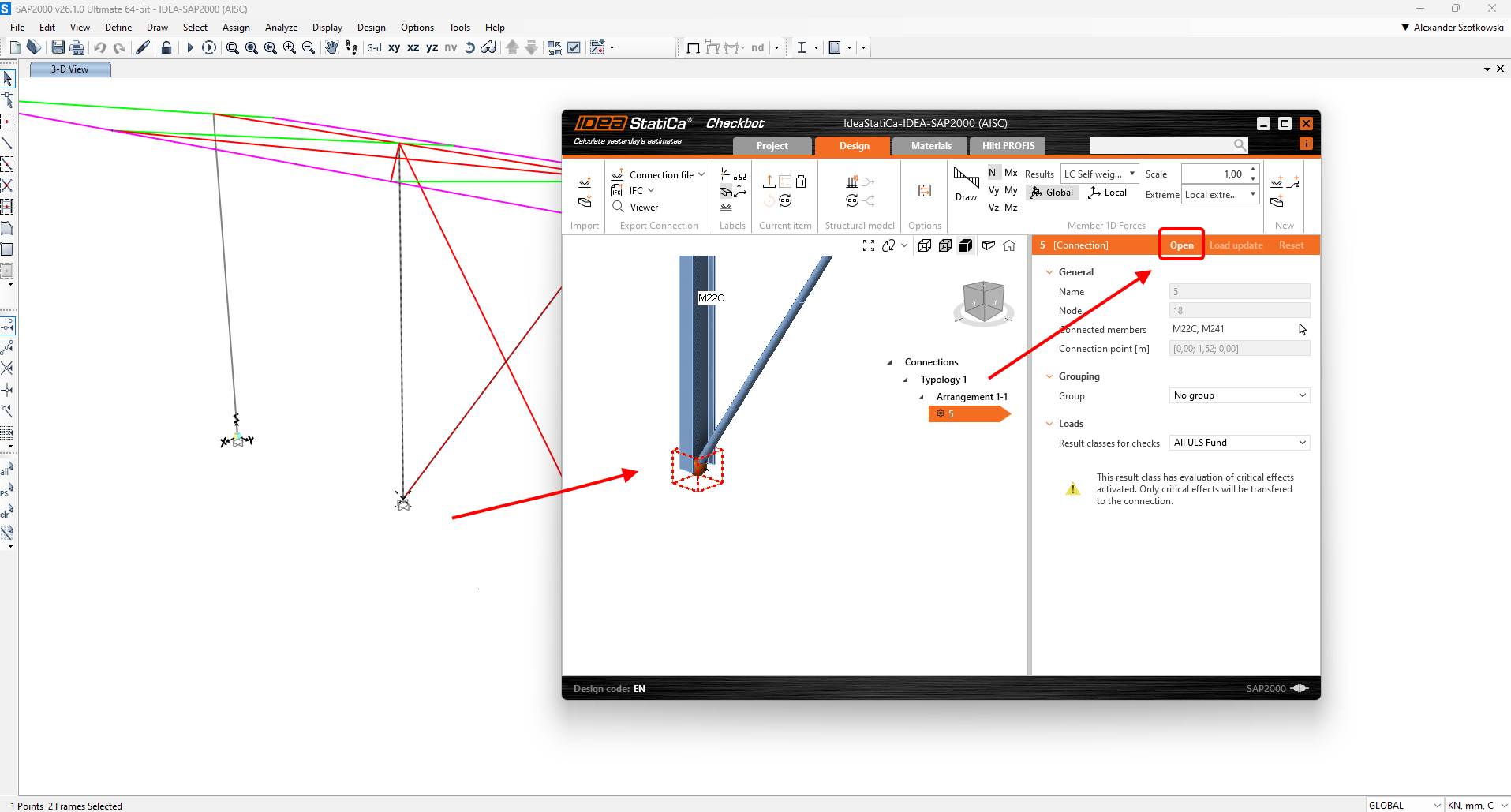
  • Open the FEA model, perform the calculation, and export the relevant nodes to Checkbot.
  • Select the node you want to design and open it in Connection. This creates a new file in the subfolder "IdeaStatiCa-name_of_FEA_file/Connections/conn-node.ideaCon". 

STEP 2

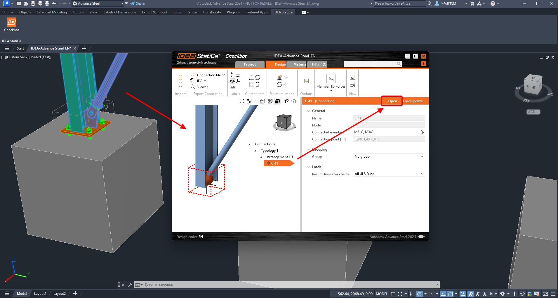
  • Open the CAD file with the same structure and export either the entire structure or the relevant nodes to Checkbot.
  • Select the same node as you did before and open it in Connection. 

STEP 3

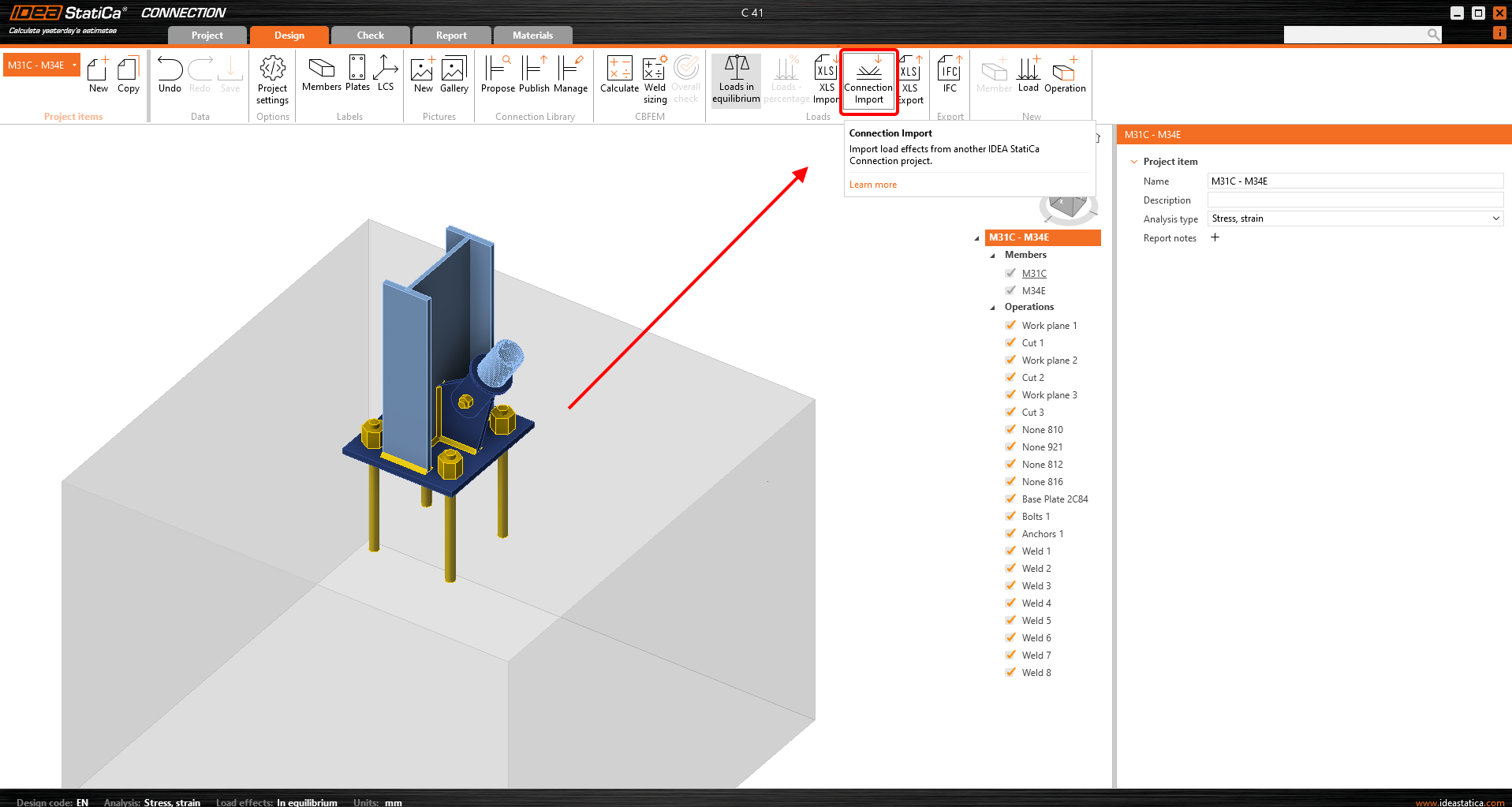
  • It's time to merge the two nodes. Simply click the Connection Import button and select the file created in Step 1.

Subscribe to our newsletter

Company

  • About us
  • Partnerships
  • Job openings
  • Patented technology for structural engineers

Resources

  • Customer projects
  • Case studies
  • IDEA StatiCa Connection Library
  • Concrete verifications

Legal

  • IDEA StatiCa END USER LICENSE AGREEMENT
  • Privacy policy
  • Terms of Services – IDEA StatiCa Viewer
  • Licensing

Help

  • Contact
  • Get price quote
  • IDEA StatiCa Specialists
  • Download the latest version
FacebookInstagramLinkedInYouTube

© IDEA StatiCa 2009-2026

Trusted and used worldwide by engineers, fabricators & consultants.