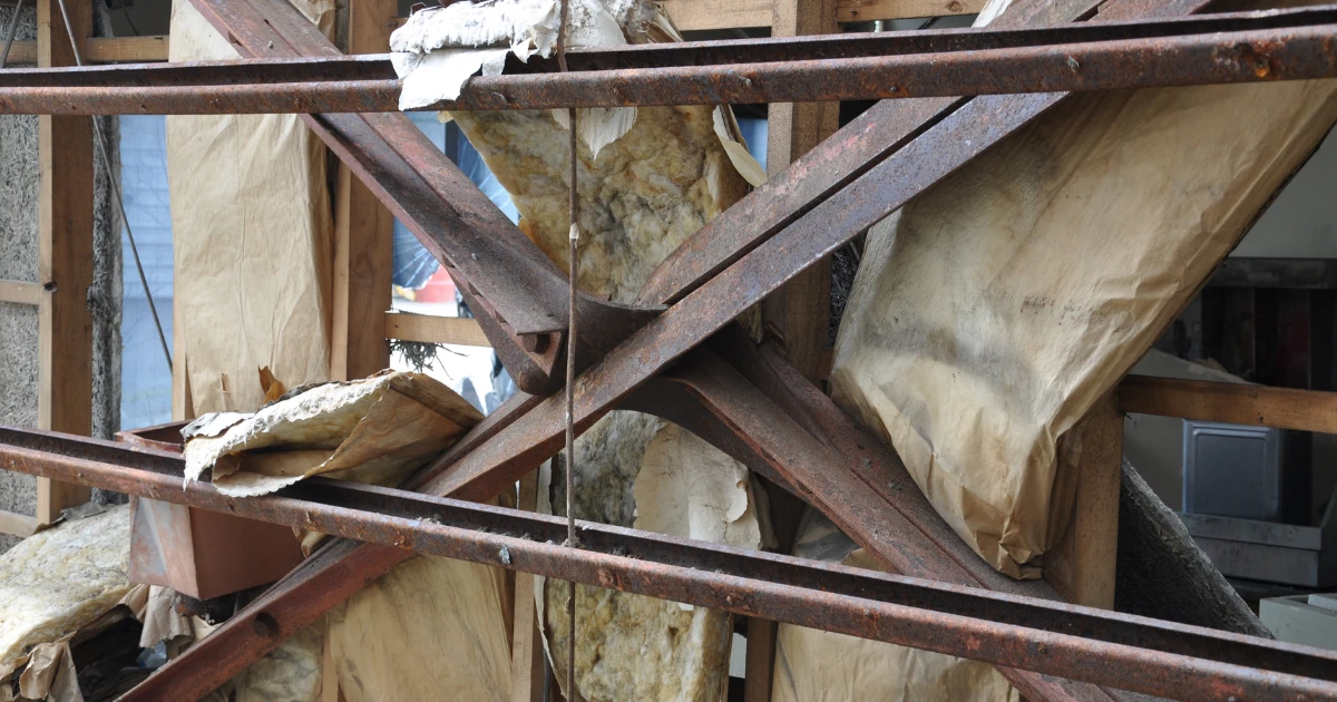


Steel is a strong, ductile, predictable material capable of supporting large spans and high slenderness. Its problem is not strength. Its problem is stability. Because steel members are so slender, they rarely fail by material yielding. They fail by buckling, often well below the cross-section's resistance, with little warning.
How the code handles stability
They give clear, well-proven guidance. EN 1993-1-1 offers a clear procedure: determine the elastic critical force Ncr and the critical moment Mcr, calculate the non-dimensional slenderness λ, select the appropriate buckling curve (a0, a, b, c, or d), read off the reduction factor χ, and check the resistance. Behind it lie decades of tests and research.
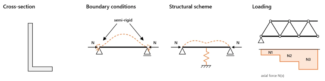
The catch is the first step. The code tells you what to do with Ncr and Mcr, but finding them is up to you, and the textbook solutions only cover:
- symmetric cross-sections,
- idealized boundary conditions,
- a simple structural scheme,
- uniform loading patterns.
Step outside these, and you're on your own. Take an asymmetric cross-section, a beam or a plate girder with unequal flanges, and the familiar formulas no longer apply. The same goes for a semi-rigid joint, an intermediate brace, or an axial force that changes along the member.
So what are your options?
Engineering judgment. Use what the code gives you, even if your case doesn't quite fit, and add your 'own safety factor' on top to be sure. A slightly longer buckling length, a lower moment factor, a bigger profile just in case.
Dedicated Mcr software. Use free tools such as LTBeam to numerically calculate the elastic critical moment of a beam.
The limits: it handles straight beams with double or mono-symmetric sections, uses a 1D beam model, and joints still have to be idealized as supports or springs whose stiffness you need to estimate.
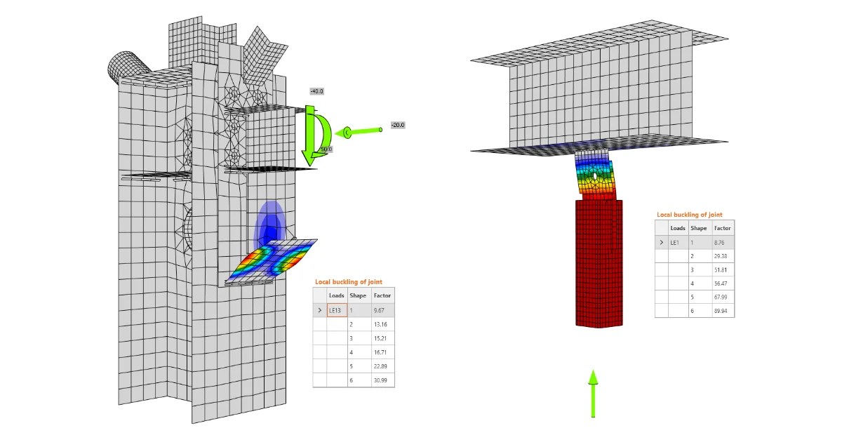
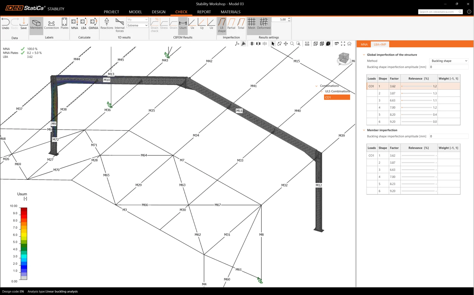
Calculate αcr. Run a linear buckling analysis (LBA) of the member on idealized supports as an eigenvalue problem. By using LBA, you can review the critical load factor αcr, the multiplier of the design load at which the perfect, elastic member buckles according to the corresponding buckling mode shapes. Then, from αcr I can get Ncr = αcr · NEd and Mcr = αcr · MEd. Then follow the standard procedure: slenderness -> buckling curve -> reduction factor -> resistance.
Go fully nonlinear with GMNIA. A geometrically and materially nonlinear analysis with imperfections captures buckling, plasticity, and imperfections directly in the model.
EN 1993-1-1 explicitly allows this: if second-order effects and the relevant member imperfections are fully accounted for in the analysis, no individual stability check of the member is needed (EN 1993-1-1:2005, clause 5.2.2(7)a).
Instead of comparing MEd with Mb,Rd or NEd with Nb,Rd, verify that the member carries 100% of the design load under the plastic strain limit. It's the most general option, and the only one that also handles openings, stiffeners, and other discontinuities. The model is more complex, the calculation takes longer, and the engineer has to choose the imperfection shape and amplitude, although the code provides rules for that as well.
LBA and GMNIA are the most accurate of these options, but they need the right tool. They are typically run in general finite element software such as ANSYS or Abaqus, which not every engineer has access to. This is exactly the gap the IDEA StatiCa Stability app fills. It runs both LBA and GMNIA, includes the real stiffness of the joints, and models openings and stiffeners directly, in a workflow built for everyday steel design.
So which cases does the code leave open?
Let’s look at a few examples from practice. They’re the kind of problems engineers can discuss for hours, comparing assumptions and arguing over buckling lengths. Or they can run an LBA, or a GMNIA where needed, and let the structure answer for itself.
Moment frame. In a sway frame, the column critical force depends on the stiffness of the joints around the member. The original estimate was Lcr = 20 m, which required IPE 400. A buckling analysis considering the stiffness of the connections gave 12 m, and an IPE 300 was sufficient.
Existing transmission towers. The towers had to carry a new, higher load, and the investor needed to know whether they could stay. The answer depended on the buckling lengths of the compressed corner members, which hinge on the stiffness of the bolted joints. With that stiffness included, Stability showed that two welded links per tower were sufficient, rather than costly strengthening. 30 existing towers were saved.
Bridge top chord on U-frames. The compressed top chord is held only by U-frames of different stiffness, while its axial force and cross-section change along the span. By hand, the buckling length took three days of work, even with ready-made spreadsheets. In Stability, it took half a day, with the same accuracy.
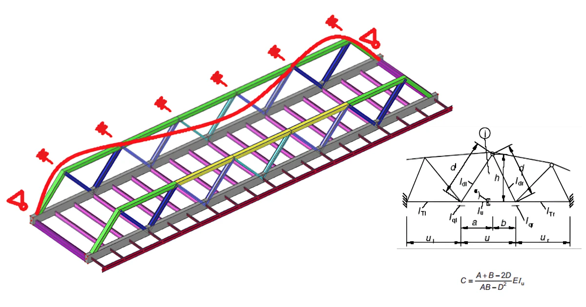
The compressed bottom chord of a roof truss
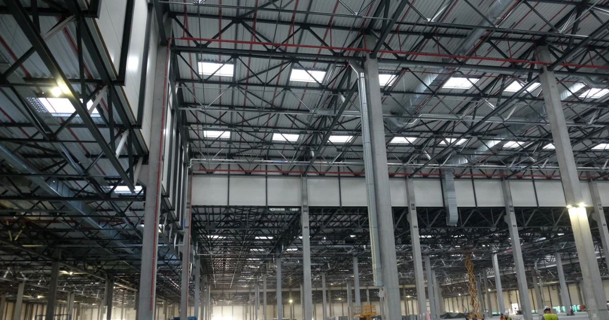
Take a large industrial hall: fixed reinforced concrete columns, and a steel roof made of trusses and purlins. To provide the transverse stiffness of the whole building, the bottom chords of the trusses had to be connected to the columns as well. As a result, part of the bottom chord went into compression.
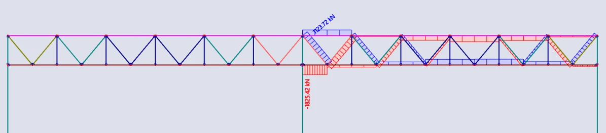
In the plane of the truss, the buckling length is clear: the chord is held at the truss nodes. But what about out of plane? Is it 0.7 L? 1.0 L? 2.6 L? Or even more?
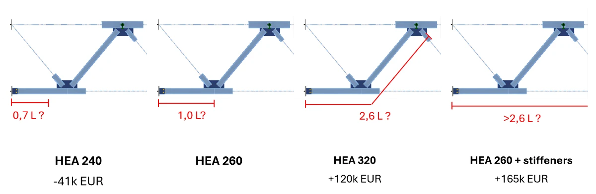
The first instinct of any structural engineer is to take the most conservative value and move on. But in a hall this size, that instinct has a price. The difference between the buckling length assumptions meant the difference between HEA 260 and HEA 320 chords, an extra € 120,000. In the worst case, to be truly sure of the buckling length, additional struts would have to be added, at an even higher cost.
Solving it in the Stability application
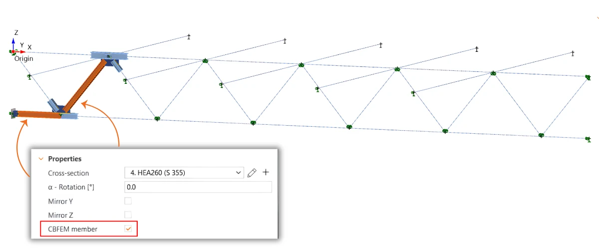
Model the truss. The truss is modeled in the Stability app, including its chords and diagonals, along with the purlins attached to the top chord. The purlins extend on both sides of the truss and are supported at their ends, representing the connection to the neighboring trusses. The truss is then loaded with the load case that causes compression in the bottom chord. Or, more simply, the results are exported from the FEA model.
Set the boundary conditions and check the internal forces. Supports are defined at the truss ends and at the ends of the purlins. Before proceeding further, the internal forces from the beam analysis are checked to ensure that the bottom chord is in compression and that the model behaves as expected.
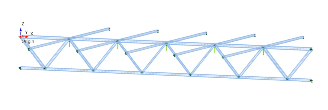
Define the CBFEM members. This is the key step. The members that matter for the stability of the chord are switched to CBFEM members. Instead of 1D members, each member is modeled with shell elements, so the model captures the actual cross-section, including its flanges and web. The connections between these members are modeled the same way, with their plates, bolts, and welds. The model therefore reflects not idealized pins or fixed ends, but the real stiffness of the joints and, with it, the real behavior of the structure.
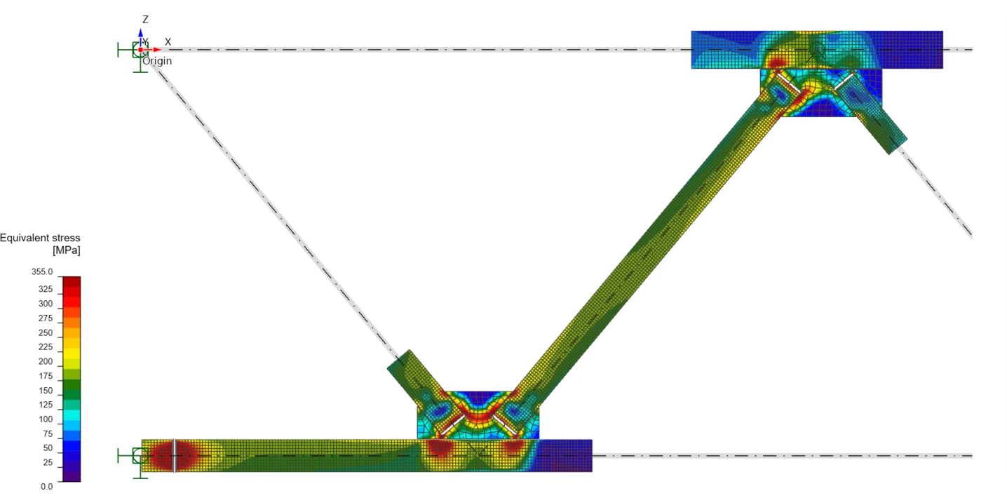
Run MNA. A materially nonlinear analysis checks that the structure carries the design load without exceeding the plastic strain limit, i.e., that its strength is sufficient.
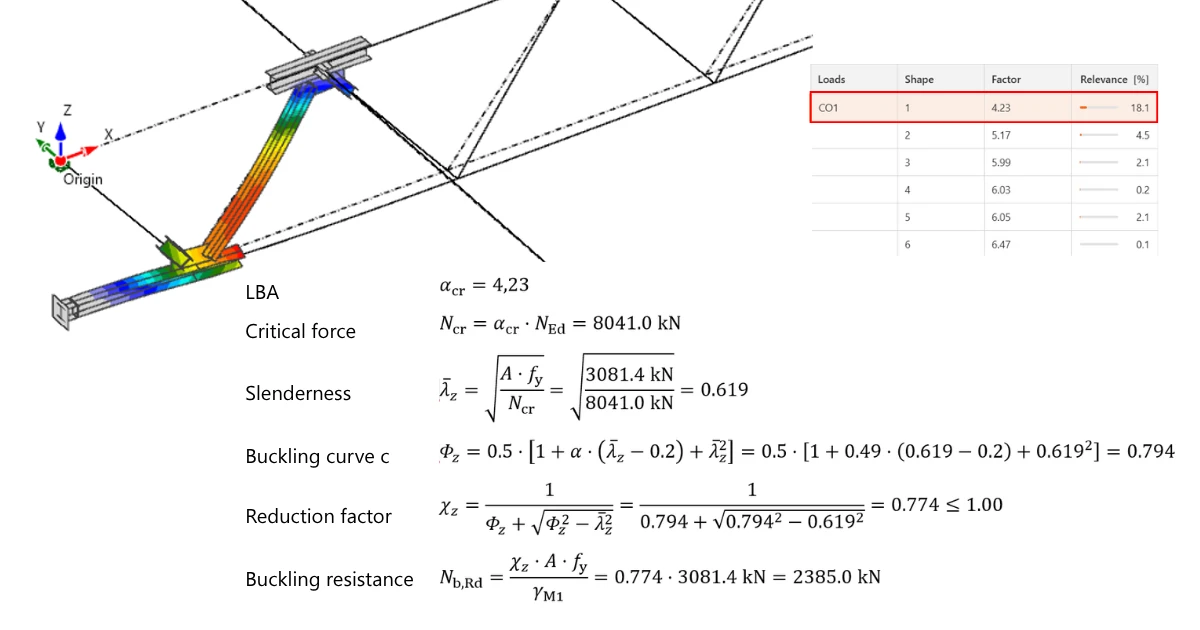
Run LBA. The linear buckling analysis then finds the buckling modes and their critical load factors αcr. For the bottom chord, the relevant one is the out-of-plane buckling mode. From its αcr, the critical force follows as Ncr = αcr · NEd, and from Ncr, the buckling length of the chord.
Check the member. The bottom chord is checked by the standard code procedure: slenderness, buckling curve, reduction factor, and buckling resistance, compared with the design axial force.
Results
The result for this case was 1.27 L, only slightly more than 1.0 L and less than half of the conservative 2.6 L. Compared to the original design with HEA 320 chords, this saved the investor around €120,000, for about two hours of work. It also made additional struts unnecessary. From a structural point of view, struts would have given the most certainty about the out-of-plane buckling length, but they would also have been the most expensive option, adding around €165,000.
Where Stability helps
The same approach works wherever the code leaves the critical load open:
- Buckling lengths of members with intermediate restraints, varying axial force or semi-rigid joints, calculated from αcr instead of estimated.
- Critical moments for lateral-torsional buckling of beams with real end connections, partial restraints or loads on the top flange, without hunting for the right moment factors.
- Existing structures, where a more accurate calculation can show that the structure is sufficient, or that a small, targeted strengthening is enough.
- Discontinuities such as web openings, castellated beams, or stiffeners, where the member no longer behaves as a simple bar, are checked directly by GMNIA.
Stop guessing your buckling lengths
Try the Stability app on your own project and see what your structure can really carry.