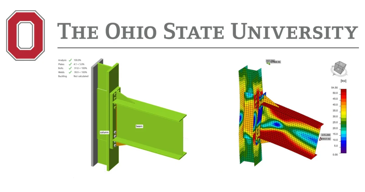
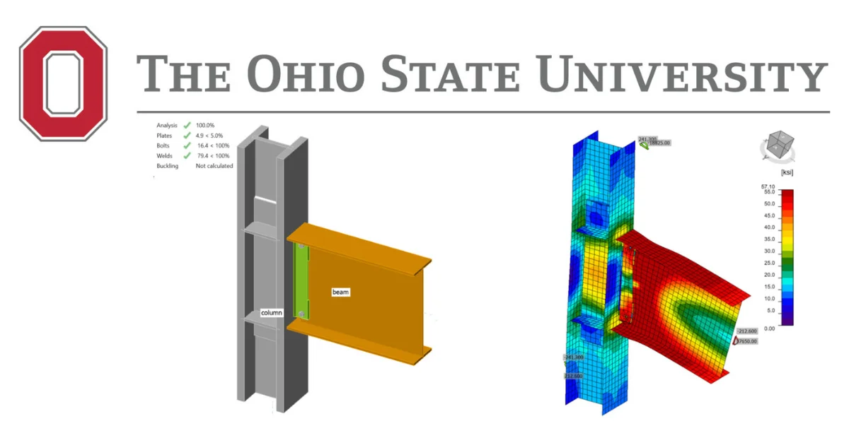
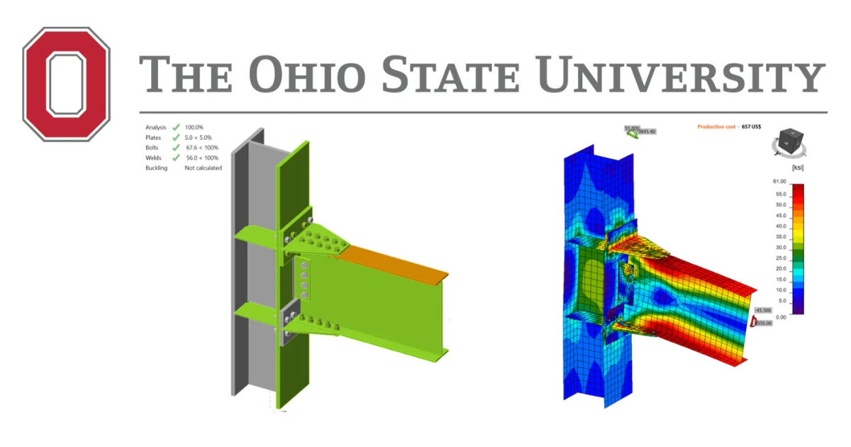
Introduction
Special Concentrically Braced Frames (SCBFs) comprise about 40 percent of the buildings in California and the trend for their use is believed to be increasing (Seyedbabak, 2017) (Chen, 2010). SCBF is a preferred Lateral Force Resisting System (LFRS) for moderate to high seismic zones (AISC 341, 2016).
This verification example was prepared in a joint project between the University of Illinois at Chicago and IDEA StatiCa. This work was conducted by:

Goal of the Project
The objective of this project was to evaluate the behavior of seismic bracing connections obtained from the IDEA StatiCa software package considering capacity design, wherein the brace members that are considered as the “fuse” for Special Concentrically Braced Frames (SCBFs) are expected to undergo significant inelastic plastic deformation for the action of the governing seismic load case.
For the presented study, two connections – a corner connection and two-story X-bracing connection, which are common in Special Concentrically Braced Frame (SCBF) system, are analyzed using CBFEM and verification with AISC is performed.

Verification Project Structure
- For each connection type, one baseline model was created, matching the design details as per AISC 341-16.
- Following the requirements given in AISC 341 (2016) and AISC 360 (2016), the design checks were performed for each connection type for the considered limit states in the connection only.
- The same specimens were modeled and analyzed in IDEA StatiCa, and their design resistance and failure modes were evaluated.
- The capacity design analysis was performed using IDEA StatiCa, and the obtained value as per CBFEM was compared with the values as obtained from traditional method based on AISC 360 and AISC 341.
- Several parametric studies were conducted for the presented connection, to understand the behavior of the connection for buckling, variation of weld, and influence of reinforcement plates on the brace member, which are essential requirements for analysis and design of seismic bracing connections.
- The results obtained from IDEA StatiCa and the AISC design calculations were evaluated, and recommendations were provided.
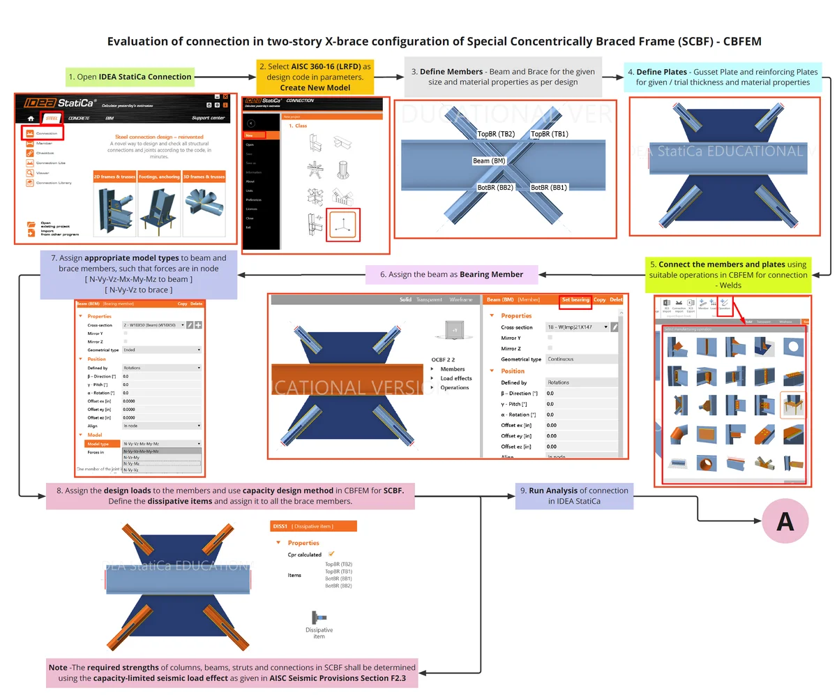
SCBF - X-Brace Connection Part 1
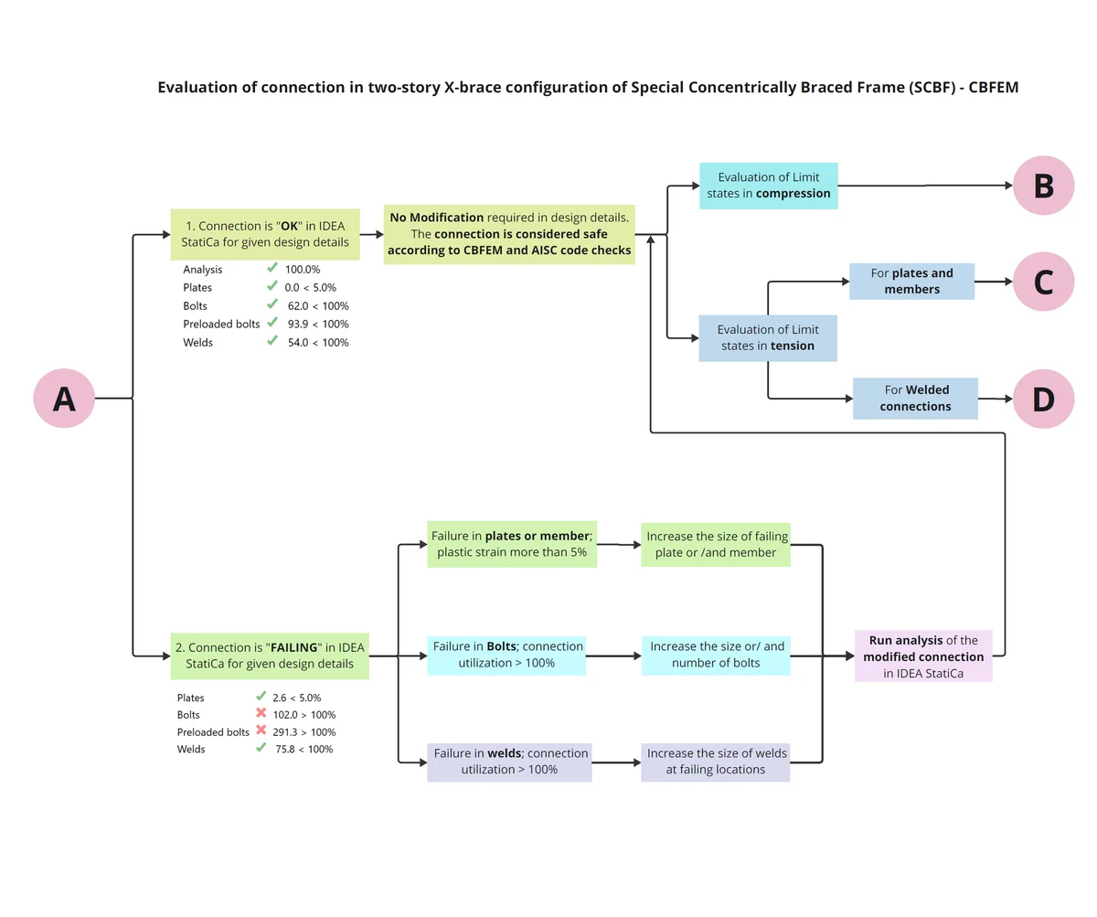
SCBF - X-Brace Connection Part 2
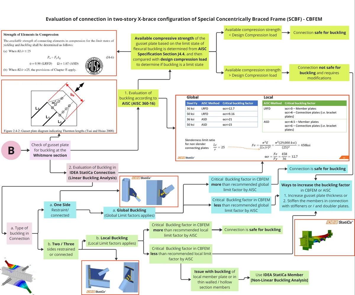
SCBF - X-Brace Connection Part 3
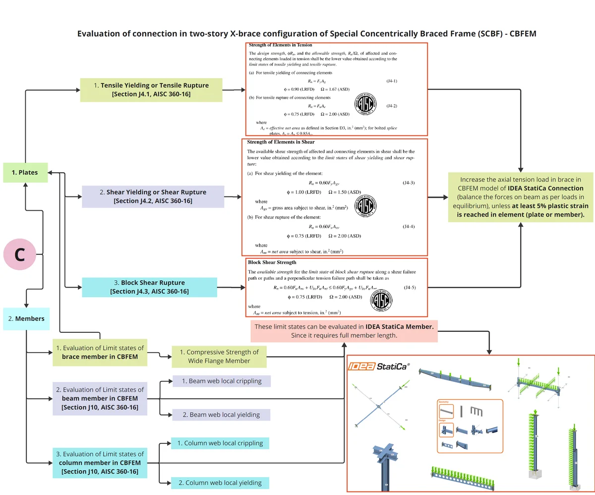
SCBF - X-Brace Connection Part 4
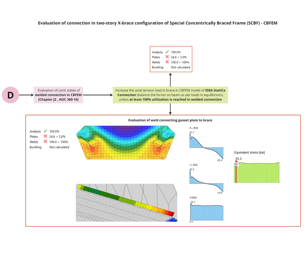
SCBF - X-Brace Connection Part 5
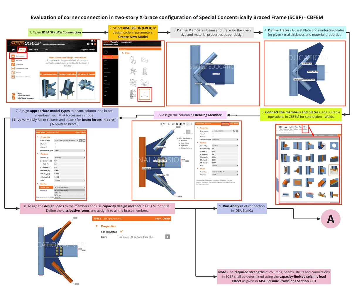
SCBF - Corner Connection Part 1
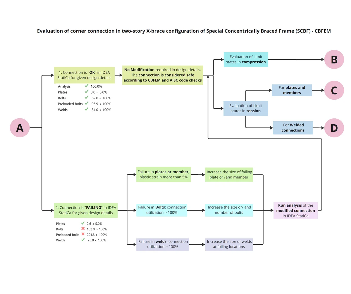
SCBF - Corner Connection Part 2
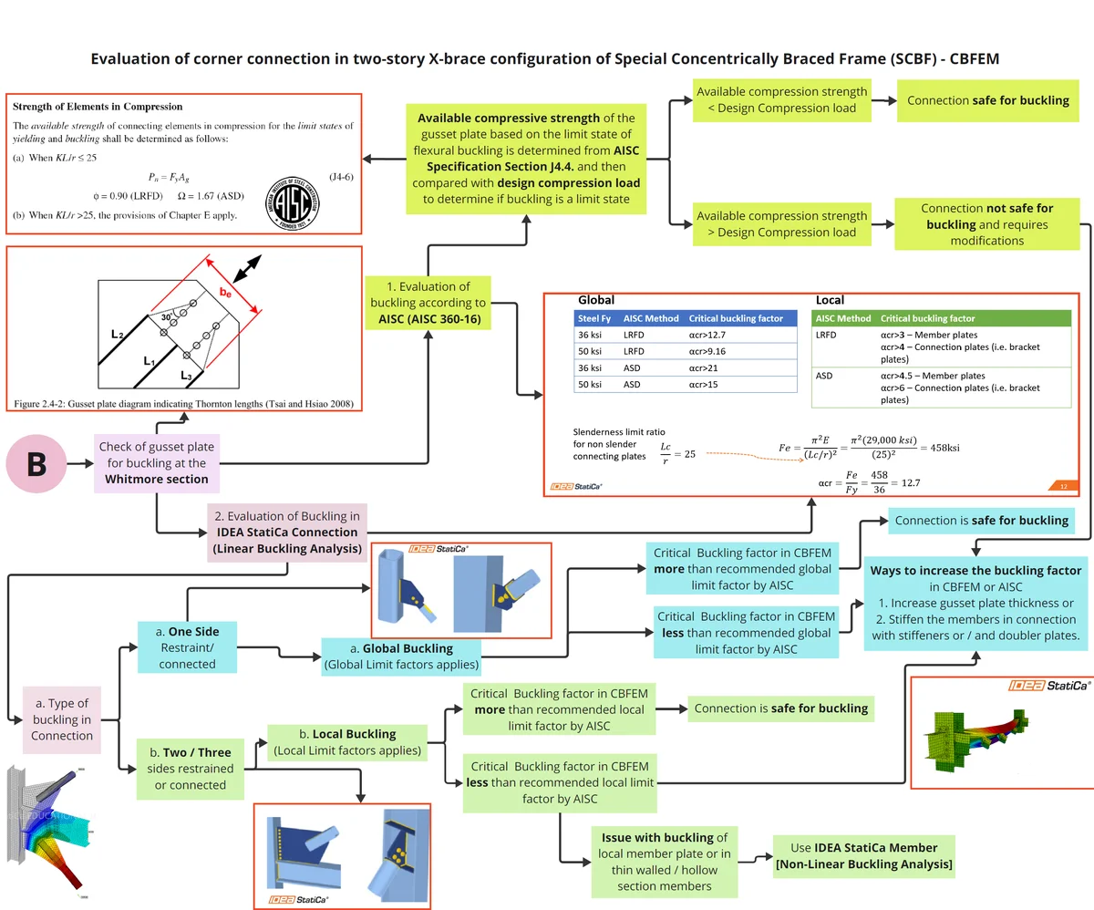
SCBF - Corner Connection Part 3
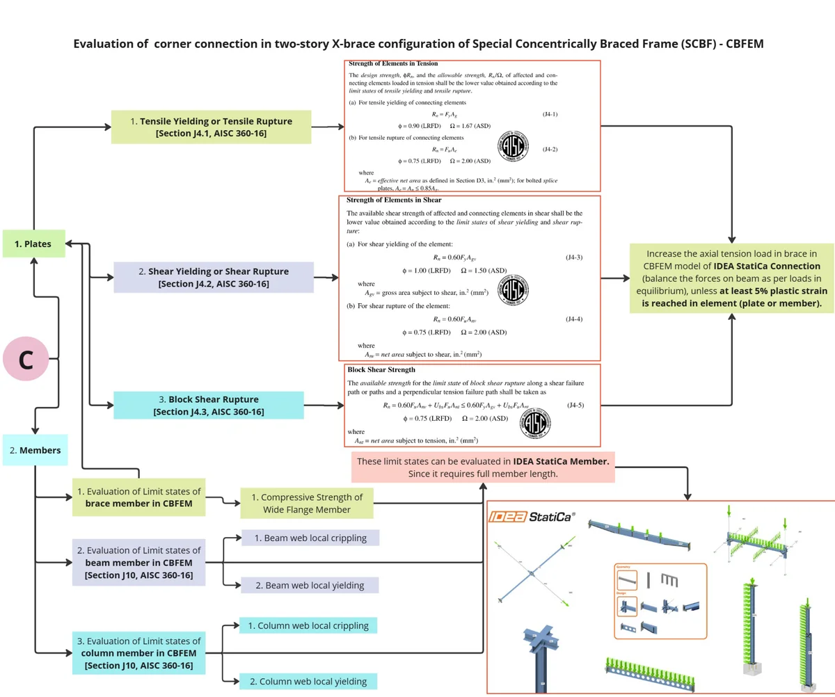
SCBF - Corner Connection Part 4
Summary
The verification studies performed by UIC demonstrated that the Component-Based Finite Element Method (CBFEM) implemented in IDEA StatiCa is capable of accurately predicting the behavior and failure modes of multi-story X-brace and corner brace-to-beam/column connections in Special Concentrically Braced Frames (SCBF). The analysis results showed close agreement with the provisions of AISC 360-16 and AISC 341-16, while also providing valuable insight into strain progression, localized failures, and capacity margins. This confirms the reliability of CBFEM not only as a code-checking tool but also as a means of understanding the actual structural response under seismic demands.
One key observation across both studies was the difference between equivalent plastic strain and maximal equivalent plastic strain obtained in the capacity design. Although both measures produced consistent trends, their discrepancies suggest that further research is necessary to better define their interpretation in connection evaluation. Another important finding was that weld capacities predicted by CBFEM were slightly higher than those obtained from AISC hand calculations. This conservatism arises because IDEA StatiCa divides welds into multiple short segments and evaluates the most critical segment, often located at the weld ends where local stress concentrations are highest. Consequently, the program produces larger weld angles and higher required weld sizes than traditional AISC methods, which assume uniform load distribution along the weld length.
The evaluation of gusset plate buckling under compression loads revealed that buckling was not a governing limit state in either AISC or CBFEM calculations, confirming adequate strength against compression-related failures. However, CBFEM provided a more refined representation of local buckling modes by capturing restraint conditions and load transfer mechanisms in detail. Additionally, the inclusion of reinforcing plates on brace members was shown to significantly improve seismic performance for the action of tension load in brace by redistributing inelastic demands away from the connection region, thereby enhancing both capacity and ductility of brace connections.
In summary, IDEA StatiCa tends to provide slightly conservative results when compared to AISC hand calculations because it explicitly accounts for effects such as local stress concentrations, three-dimensional load transfer mechanisms, nonlinear plastic redistribution, and weld eccentricities—factors that are often neglected in simplified design equations. While this may lead to larger required welds the conservatism enhances safety and offers engineers a more realistic picture of structural performance. Together, these studies validate CBFEM as a reliable, practical, and insightful framework for evaluating SCBF brace connections, complementing traditional design provisions while improving confidence in seismic design outcomes.
Summary of Results
Verification Example 1 – X Bracing Connection
1. Evaluation of Limit State for Tension Load in Brace
| Sr No | Limit State of | AISC (kips) | CBFEM (kips) | ∆AISC_CBFEM(%) |
| 1 | Tensile Yielding of Gusset Plate – Above Beam | 420 | 467.5 | 11.2 |
| 2 | Block Shear Rupture of Gusset Plate – Above Beam | 484 | 500 | 3.2 |
| 3 | Tensile Yielding of Gusset Plate – Below Beam | 605 | 620 | 2.4 |
2. Comparison of weld sizes as per AISC and CBFEM
| Sr No. | Pbrace (kips) | Check of weld connecting | Required ‘16ths weld size (in) | |
| AISC | CBFEM | |||
| 1 | 335 | Reinforcing plate and brace – Above Beam | 5 | 6 |
| 2 | 370 | Reinforcing plate and brace – Below Beam | 5 | 6 |
| 3 | 410 | Gusset Plate and Brace – Above Beam | 4 | 5 |
| 4 | 445 | Gusset Plate and Brace – Below Beam | 4 | 5 |
| 5 | 546 | Gusset Plate to Top Flange of Beam | 4 | 5 |
| 6 | 620 | Gusset Plate to Bottom Flange of Beam | 7 | 8 |
where, Pbrace is axial load in brace for which weld percentage utilization is 100% in CBFEM.
Verification Example 2 – Corner Connection with Beam Stub
1. Evaluation of Limit State for Tension Load in Brace
| Sr No | Limit State of | AISC (kips) | CBFEM (kips) | ∆AISC_CBFEM(%) |
| 1 | Tensile yielding of top gusset plate | 871 | 930 | +6.3 |
| 2 | Tensile yielding of bottom gusset plate | 945 | 990 | +4.5 |
2. Comparison of weld sizes as per AISC and CBFEM
| Sr No. | Pbrace (kips) | Check of weld connecting | Required ‘16ths weld size (in) | |
| AISC | CBFEM | |||
| 1 | 449 | Brace-to-gusset plate above beam | 4 | 5 |
| 2 | 466 | Brace-to-gusset plate below beam | 4 | 5 |
| 3 | 663.8 | Reinforcing plate-to-brace above beam | 4 | 5 |
| 4 | 720 | Column flange-to-gusset plate below beam | 7 | 8 |
| 5 | 723.5 | Reinforcing plate-to-brace below beam | 4 | 5 |
| 6 | 842 | Bottom flange of beam to gusset plate | 7 | 8 |
| 7 | 895 | Top flange of beam to gusset plate | 8 | 9 |
| 8 | 906 | Column flange-to-gusset plate above beam | 8 | 9 |
Where, Pbrace is axial load in brace for which weld percentage utilization is 100% in CBFEM.
Read the full study examples:
References
AISC 341. (2016). Seismic Design Manual. American Institute of Steel Construction, Chicago, Illinois.
AISC 360. (2016). Specification for Structural Steel Buildings. American Institute of Steel Construction, Chicago, Illinois.
Ebrahimi, S., & Mirghaderi, S. R. (2021). Designing gusset plates of chevron-SCBFs through a new method. The Structural Design of Tall and Special Buildings, 30(5), e1835. https://doi.org/10.1002/tal.1835
Marcu, R., & Köber, H. (2021). Seismic design methods for concentrically braced frames. IOP Conference Series: Earth and Environmental Science, 664(1), 012086. https://doi.org/10.1088/1755-1315/664/1/012086
Roeder, C. W., Lumpkin, E. J., & Lehman, D. E. (2011). A balanced design procedure for special concentrically braced frame connections. Journal of Constructional Steel Research, 67(11), 1760–1772. https://doi.org/10.1016/j.jcsr.2011.04.016
Simpson, B. G., & Mahin, S. A. (2018). Experimental and Numerical Investigation of Strongback Braced Frame System to Mitigate Weak Story Behavior. Journal of Structural Engineering, 144(2), 04017211. https://doi.org/10.1061/(ASCE)ST.1943-541X.0001960
Sizemore, J. G., Fahnestock, L. A., Hines, E. M., & Bradley, C. R. (2017). Parametric Study of Low-Ductility Concentrically Braced Frames under Cyclic Static Loading. Journal of Structural Engineering, 143(6), 04017032. https://doi.org/10.1061/(ASCE)ST.1943-541X.0001761
AISC 341. (2016). Seismic Design Manual. American Institute of Steel Construction, Chicago, Illinois.
AISC 360. (2016). Specification for Structural Steel Buildings. American Institute of Steel Construction, Chicago, Illinois.
Bruneau, M., Uang, C.-M., & Sabelli, R. (2011). Ductile Design of Steel Structures (2nd Edition). McGraw Hill Education. https://www.accessengineeringlibrary.com/content/book/9780071623957