Introduction
Ordinary Concentrically Braced Frames (OCBFs) are designed to remain in the elastic range during a seismic event. As a result, the special requirements for the design of OCBFs are relatively few, when compared to other steel systems that are required to be designed as more ductile, such as SCBF.
This verification example was prepared in a joint project between the University of Illinois at Chicago and IDEA StatiCa. This work was conducted by:

Goal of the Project
The objective of this project was to evaluate the behavior of seismic bracing connections obtained from the IDEA StatiCa software package considering joint design resistance analysis and stress-strain analysis.
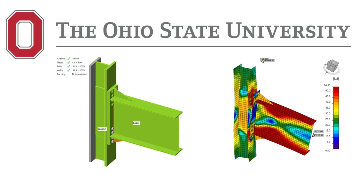
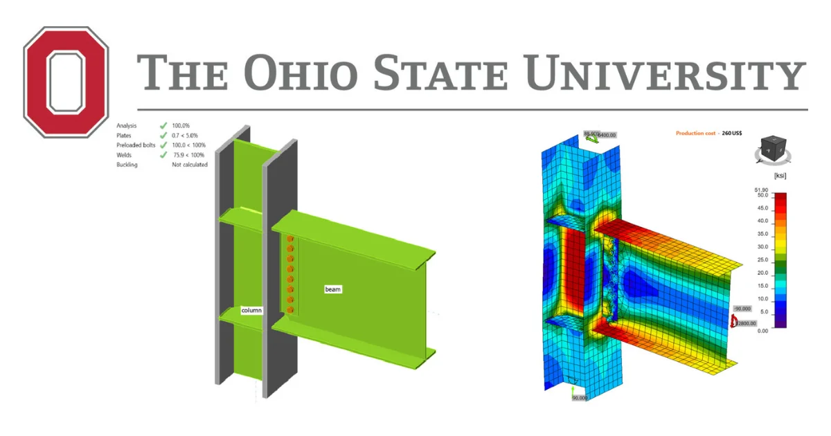
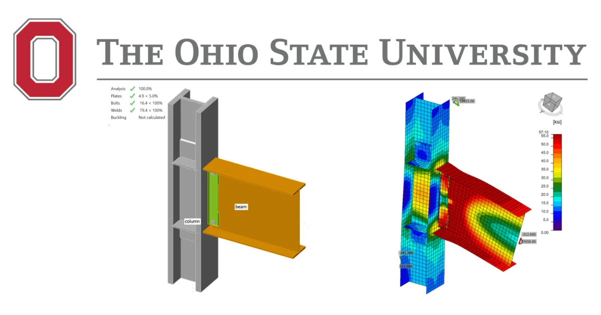
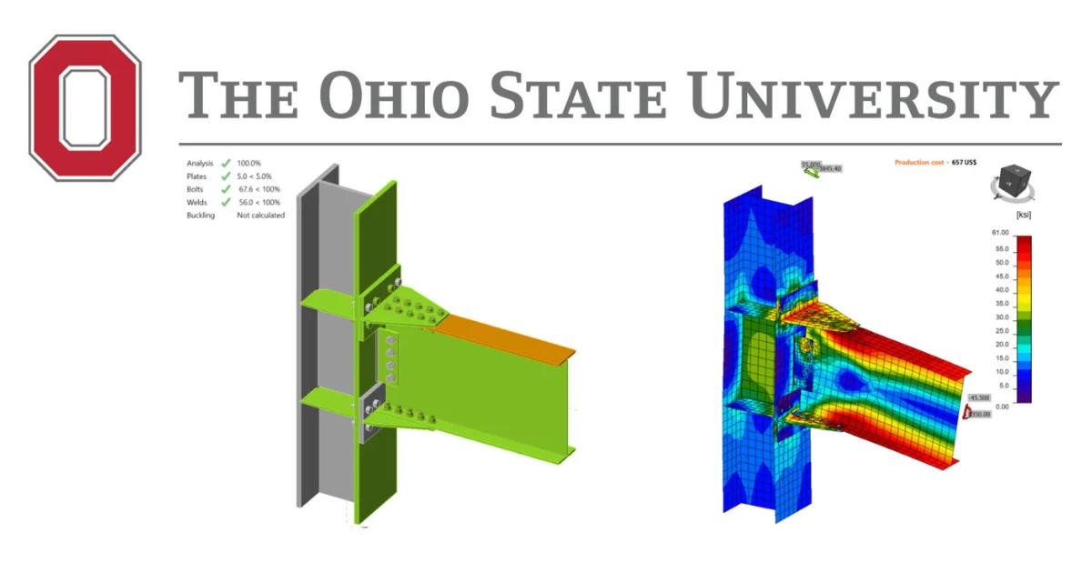
For the presented study, two connections – a corner connection and two-story X-bracing connection, which are common in an ordinary concentrically braced frame (OCBF) system, are analyzed using CBFEM and verification with AISC is performed

Verification Project Structure
- For each connection type, one baseline model was created, matching the design details as per AISC 341-16.
- Following the requirements given in AISC 341 (2016) and AISC 360 (2016), the design checks were performed for each connection type for the considered limit states in the connection only.
- The same specimens were modeled and analyzed in IDEA StatiCa, and their joint design resistance and failure modes were evaluated.
- The stress-strain analysis was performed using IDEA StatiCa, and the obtained value as per CBFEM was compared with the values as obtained from the traditional method based on AISC 360 and AISC 341.
- Several parametric studies were conducted for the presented connection, to understand the behavior of the connection for buckling, variation of weld and influence of reinforcement plates on the brace member, which are essential requirements for analysis and design of seismic bracing connections.
- The results obtained from the IDEA StatiCa and AISC design calculations were evaluated, and recommendations were provided.
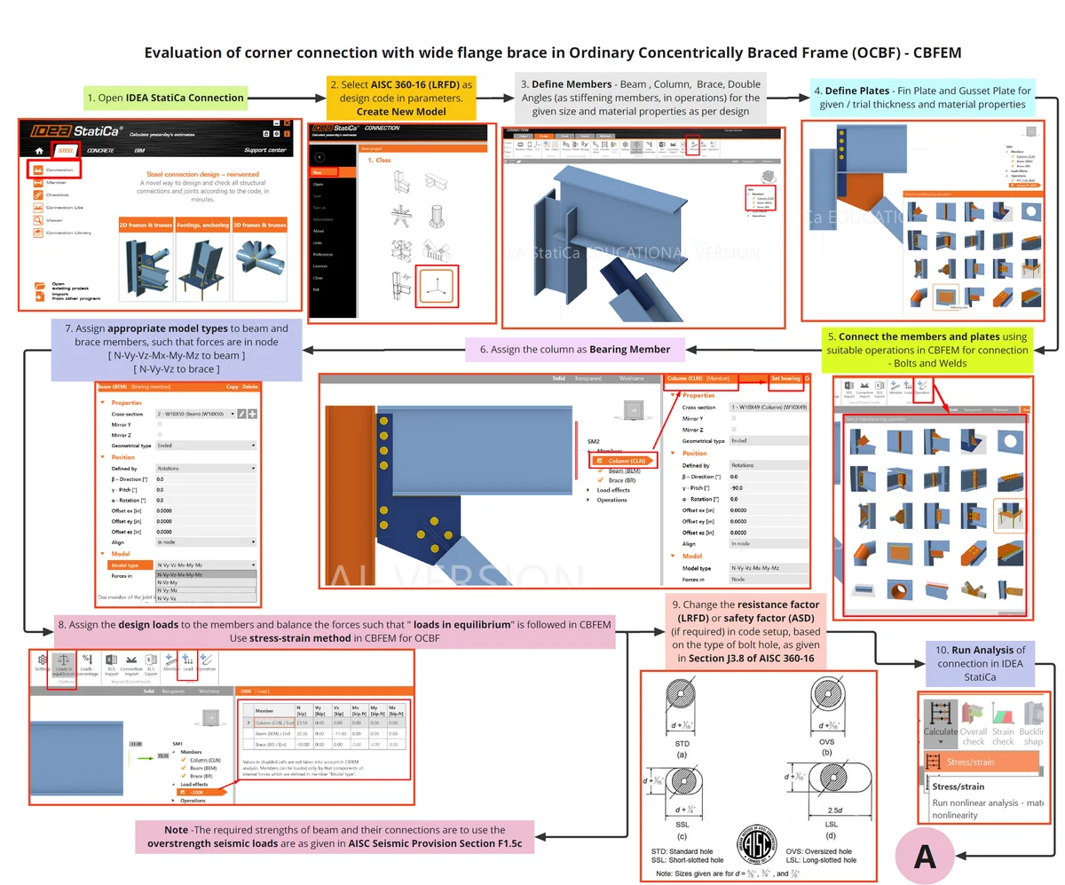
OCBF - Corner Connection Part 1
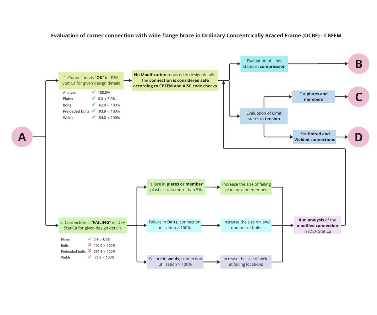
OCBF - Corner Connection Part 2
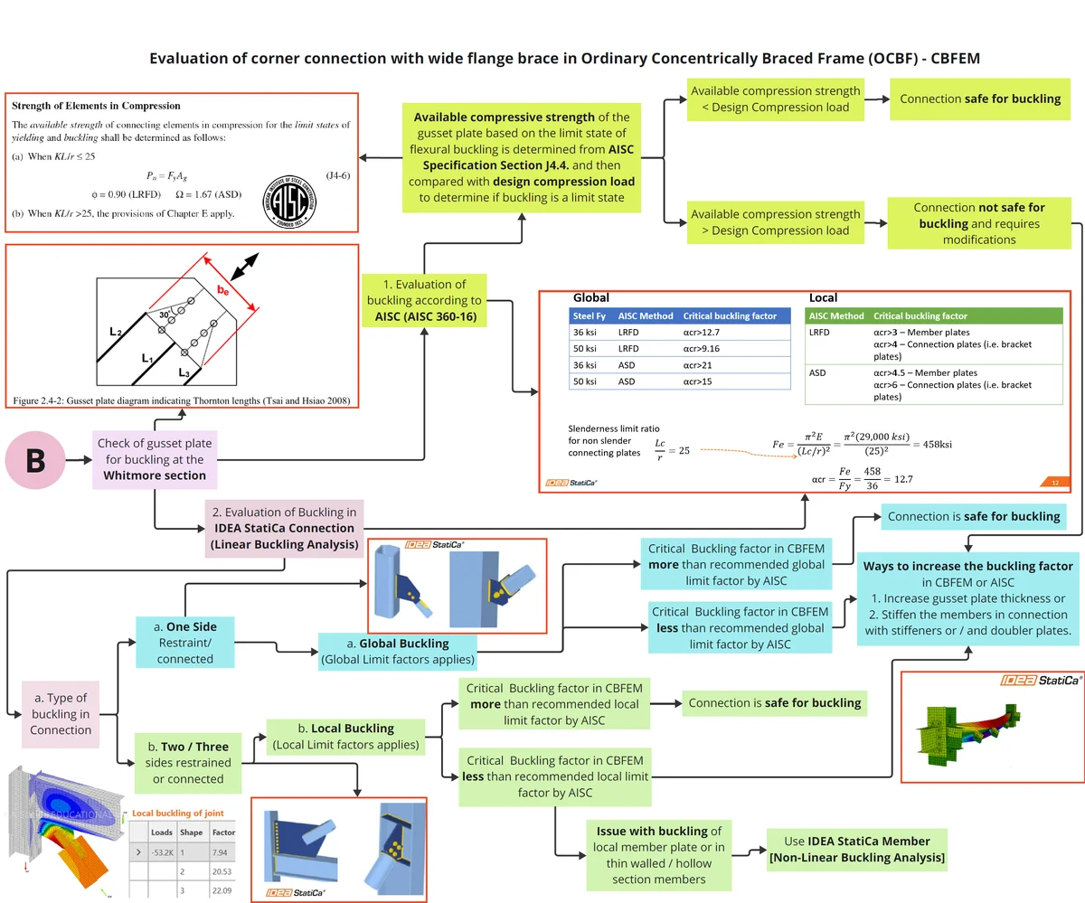
OCBF - Corner Connection Part 3
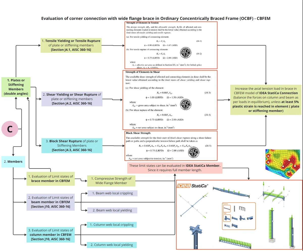
OCBF - Corner Connection Part 4
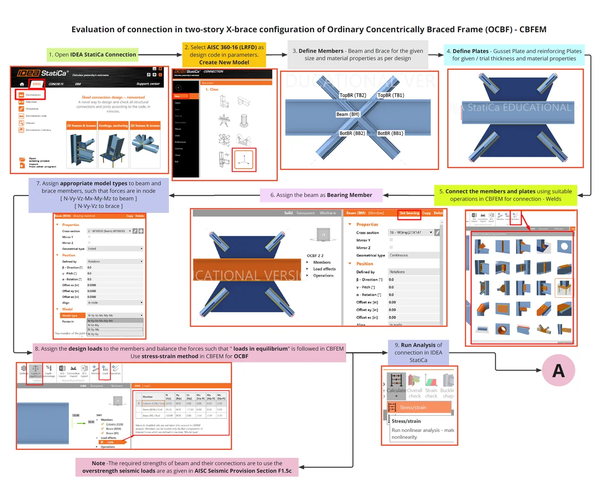
OCBF - X-Brace Connection Part 1
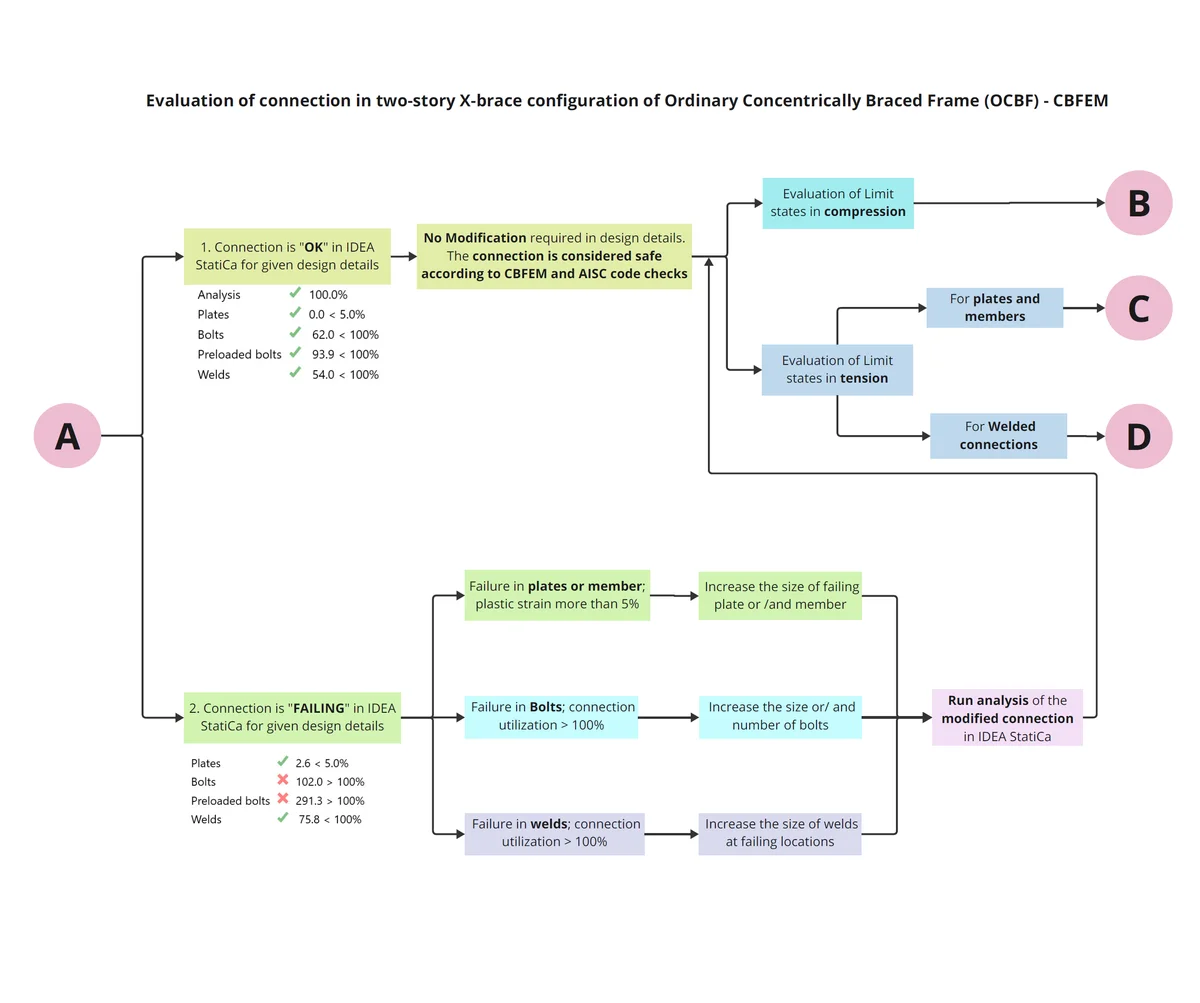
OCBF - X-Brace Connection Part 2
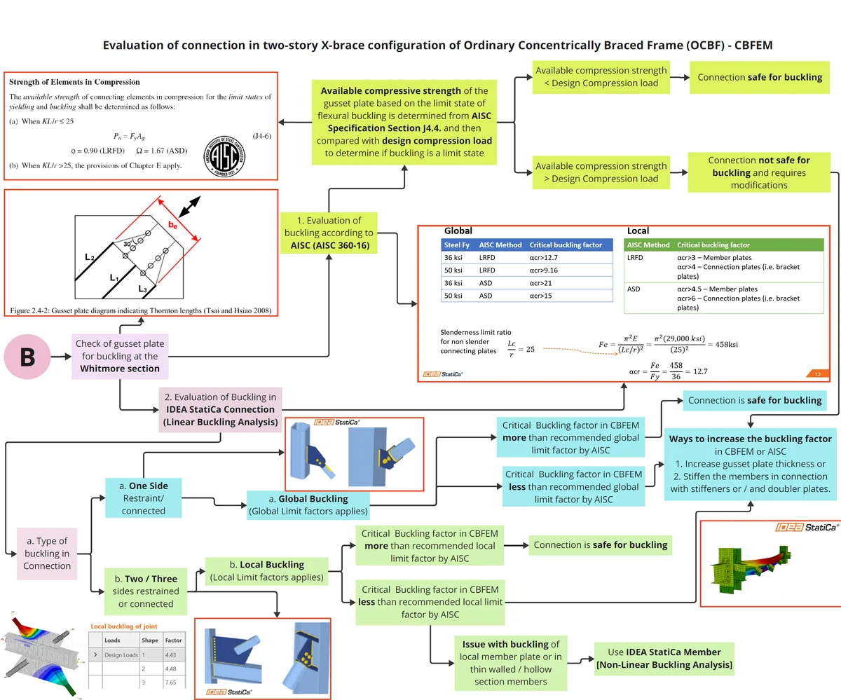
OCBF - X-Brace Connection Part 3
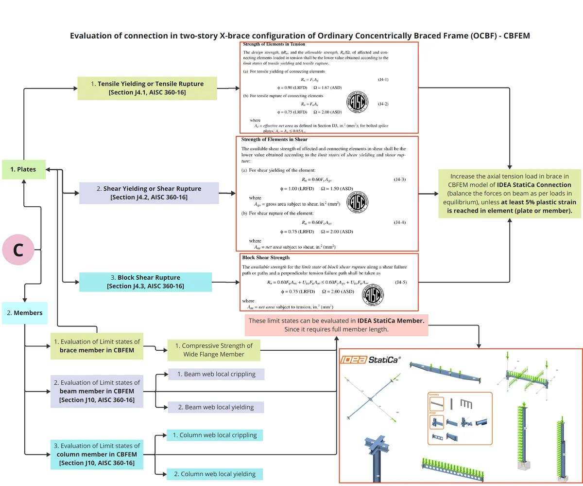
OCBF - X-Brace Connection Part 4
OCBF - X-Brace Connection Part 5
Summary
The UIC study on seismic bracing connections in OCBFs demonstrated that the application of the Component-Based Finite Element Method (CBFEM) in IDEA StatiCa provides a reliable and practical approach for evaluating connection performance. The software captured most governing limit states with good accuracy, showing deviations of only 7%–10% from AISC provisions, and tended to be slightly conservative in certain cases. Beyond close numerical agreement, CBFEM effectively predicted the actual behavior and failure modes of the connections, offering valuable insights into reserve strength, stress–strain response, and limit state progression.
Key observations include that compression limit states were not governing, as brace resistance under compression was higher than under tension. Bolt bearing checks were found to be conservative since CBFEM evaluates each bolt individually. For gusset plates, yielding and rupture were assessed using a 5% plastic strain criterion, while block shear calculations—based solely on yield strength rather than both yield and rupture strength as in AISC—were also conservative. Buckling of gusset plates under brace compression was not observed as a controlling limit state, consistent with AISC provisions. Beam web-related limit states (buckling, crippling, shear yielding) were excluded since they occur only at high loads levels beyond model convergence. Weld strength predictions matched AISC, with critical utilization typically concentrated at weld terminations. Minor mesh dependency was observed in bolt and weld utilization, though this did not affect overall conclusions.
Although some bolted elements showed large percentage differences between CBFEM and AISC checks, these are not critical to connection performance. This is primarily because CBFEM evaluates bolt bearing on each individual bolt rather than for the connection as a whole, which produces more conservative results without affecting the adequacy of the design. Likewise, member limit states (such as beam web buckling, crippling, and shear yielding) are not governing for the seismic performance of the studied connections, as they occur only at load levels beyond the range of interest and were therefore not considered for the evaluation.
Overall, IDEA StatiCa using CBFEM proved to be a dependable and accurate tool for assessing seismic bracing connections in OCBFs, providing not only close correlation with AISC design checks but also enhanced insight into connection behavior, reserve capacity, and governing limit states.
Summary of Results
Verification Example 1 – Corner Connection with Wide flange brace
1. Evaluation of Limit States
| Sr No. | Limit State of | AISC (kips) | CBFEM (kips) | % difference | Related to | Comment |
| 1 | Bolt bearing and tear out on angles | 64 | 60 | -6.3% | Connection | CBFEM is slightly conservative. |
| 2 | Bolt bearing and tear out on brace web (SS) | 64 | 60 | -6.3% | Connection | CBFEM is slightly conservative. |
| 3 | Bolt bearing and tear out on plate (SS) | 64.5 | 60 | -6.3% | Connection | CBFEM slightly conservative by 6.3%. |
| 4 | Compressive strength of brace | 72 | NA | NA | Member | Not checked, as it requires full member length. Not in current scope. Possible in IDEA StatiCa Member |
| 6 | Block shear rupture of bottom brace web | 124 | 110 | -19% | Connection | CBFEM very conservative. |
| 7 | Beam web local crippling | 131 | NA | NA | Member | Not a controlling limit state |
| 8 | Block shear rupture in the gusset plate | 164 | 115 | -42% | Connection | CBFEM results conservative – not a controlling limit state |
| 9 | Block shear rupture in the angles | 170 | 115 | -49% | Connection | CBFEM results conservative – not a controlling limit state |
| 10 | Tensile rupture in the angles | 240 | 110 | -129% | Connection | CBFEM results conservative – not a controlling limit state |
| 10 | Beam web local yielding | 265 | NA | NA | Member | Not a controlling limit state |
| 11 | Tension yielding in the angles | 272 | 110 | -147% | Connection | CBFEM results conservative – not a controlling limit state |
| 12 | Tensile Rupture strength of bottom brace web | 285 | 110 | -159% | Connection | CBFEM results conservative – not a controlling limit state |
| 13 | Column web local crippling | 286 | NA | NA | Member | Not a controlling limit state |
| 14 | Column web local yielding | 445 | NA | NA | Member | Not a controlling limit state |
2. Comparison of weld sizes as per AISC and CBFEM
| Sr No. | Pbrace (kips) | Check of weld connecting | Required ‘16ths weld size (in) | |
| AISC | CBFEM | |||
| 1 | 94 | Fin plate to column | 4 | 4 |
| 2 | 171 | Gusset plate to beam | 4 | 4 |
where, Pbrace is axial load in brace for which weld percentage utilization is 100% in CBFEM.
Verification Example 2 – X Bracing Connection
1. Evaluation of Limit State for Tension Load in Brace
| Sr No | Limit State of | AISC (kips) | CBFEM (kips) | ∆AISC_CBFEM (%) |
| 1 | Tensile Yielding of Gusset Plate | 450 | 476 | 6% |
| 2 | Block Shear Rupture of Gusset Plate | 480 | 485 | 1% |
| 3 | Bolt Shear | 51 | 51 | 0% |
| 4 | Bolt Bearing | 61 | 61 | 0% |
| 5 | Bolt Tearout | OK | OK | N.A |
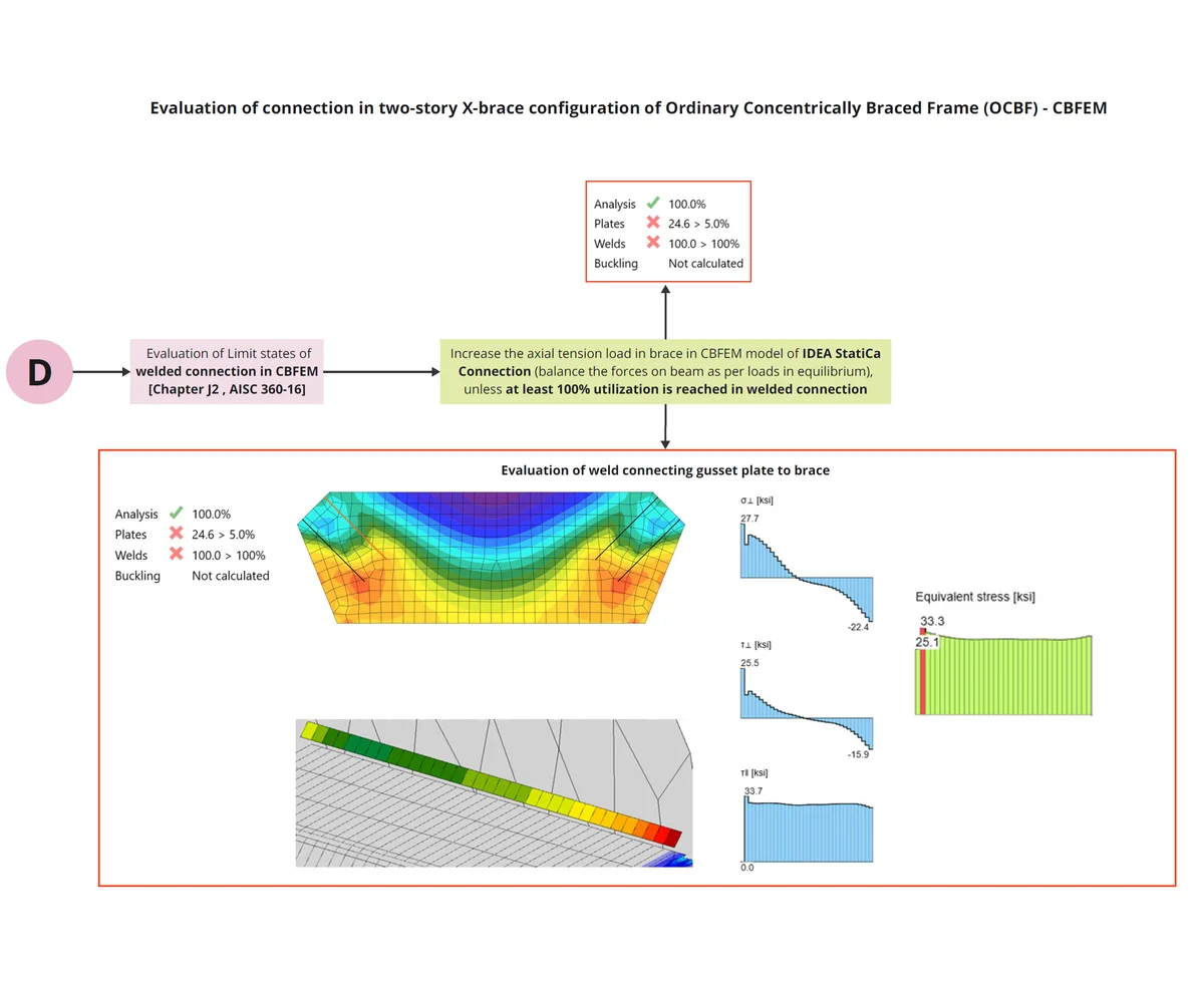
2. Comparison of weld sizes as per AISC and CBFEM
| Sr No. | Pbrace (kips) | Check of weld connecting | Required ‘16ths weld size (in) | |
| AISC | CBFEM | |||
| 1 | 505 | Gusset plate to beam top flange | 5/16 | 5/16 |
| 2 | 530 | Gusset plate to column | 5/16 | 5/16 |
| 3 | 555 | Gusset plate to lug plate | 3/8 | 3/8 |
where, Pbrace is axial load in brace for which weld percentage utilization is 100% in CBFEM.
Read the full study examples:
References
Afifi, M., Tremblay, R., & Rogers, C. (2020). SLOTTED-HIDDEN-GAP (SHG) BRACE CONNECTIONS FOR SQUARE HOLLOW STRUCTURAL SECTIONS FOR SEISMIC APPLICATIONS.
AISC 341. (2016). Seismic Design Manual. American Institute of Steel Construction, Chicago, Illinois.
AISC 360. (2016). Specification for Structural Steel Buildings. American Institute of Steel Construction, Chicago, Illinois.
Roostaeyan, E., Rasoul Mirghaderi, S., Ghazizadeh, S., & Zahrai, S. M. (2020). Through gusset connection for two-story X-braced frames, a numerical study. Structures, 27, 285–296. https://doi.org/10.1016/j.istruc.2020.05.025
Seismosoft. (2022, May 16). Steel Bracing. Seismosoft. https://seismosoft.com/steel-bracing/
AISC 360. (2016). Specification for Structural Steel Buildings. American Institute of Steel Construction, Chicago, Illinois.
AISC 341. (2016). Seismic Design Manual. American Institute of Steel Construction, Chicago, Illinois.
IDEA StatiCa. (n.d.). IDEA StatiCa Support center- FAQ. https://www.ideastatica.com/support-center-faq