Idea Statica
  • Steel
  • Concrete
  • BIM & Workflows
  • Support & Learning
  • Pricing
  • Company
  • Steel overview
  • Connection design
  • Member design
  • Parametric design
  • Steel case studies
  • Concrete overview
  • Walls and D-regions
  • Anchoring design
  • Concrete case studies
  • BIM Overview
  • Supported integrations
  • Checkbot
  • Viewer
  • APIs
  • Support Center
  • E-learning & certification
  • Blog
  • Downloads & Licensing
  • Plans
  • Free community tool
  • Enterprise customers
  • Students & educators
  • How much will you save?
  • About us
  • Contact
  • Research & development
  • Authorized resellers
  • Meet our customers
  • Career
  • Steel
    Steel overviewConnection designMember designParametric designSteel case studies
  • Concrete
    Concrete overviewWalls and D-regionsAnchoring designConcrete case studies
  • BIM & Workflows
    BIM OverviewSupported integrationsCheckbotViewerAPIs
  • Support & Learning
    Support CenterE-learning & certificationBlogDownloads & Licensing
  • Pricing
    PlansFree community toolEnterprise customersStudents & educatorsHow much will you save?
  • Company
    About usContactResearch & developmentAuthorized resellersMeet our customersCareer
14-Day Trial
14-Day Trial
  • Steel
  • Concrete
  • BIM & Workflows
  • Support & Learning
  • Pricing
  • Company

Subscribe to our newsletter

Company

  • About us
  • Partners
  • Careers
  • Patent

Resources

  • Customer projects
  • Case studies
  • Connection Library
  • Verification books

Legal

  • EULA
  • Privacy policy
  • California Privacy
  • TOS Viewer
  • Licensing

Help

  • Contact
  • Quote request
  • Resellers
  • Downloads
FacebookInstagramLinkedInYouTube

Ā© IDEA StatiCa 2009-2026

Trusted and used worldwide by engineers, fabricators & consultants.

Support CenterKnowledge Base ArticlesFatigue analysis type in structural design
Advanced analysis types for your steel structures
Fatigue analysis: nominal stress
Fatigue analysis - how the results are displayed
Fatigue analysis according to EN 1993-1-9
Fatigue analysis type in structural design
Fatigue analysis type serves to determine normal and shear stress range between two load cases. IDEA StatiCa - structural design software for modeling and code-checking steel connections.
SteelConnection designKnowledge baseAISC (USA)Bolts

Fatigue analysis type in structural design

This article is also available in
ENCZDEESFRITPTNLHUROKRPLTHTRVIZH

Fatigue analysis type serves to determine normal and shear stress range between two load cases. The stresses correspond to nominal stresses and must be further evaluated using code design methods. It is assumed to be used for the design of high-cycle fatigue details, where no yielding is expected.

The fatigue analysis type does not provide any final resistance or number of cycles the detail can take. It just provides inputs to further calculations according to codes.

Always, at least two load cases must be set. The first load case is the reference one. It is assumed as, e.g., a self-weight of the structure and can contain zero loads. The other load cases are simulating fatigue actions. The nominal normal and shear stress provided by IDEA StatiCa is the stress range between the fatigue action, e.g. LE2, and the reference load case.

For example, the shear stress at a certain location is 50 MPa in the Reference load case and 180 MPa in LE2. The shown nominal shear stress at this location is:

Ļ„=180āˆ’50=130 MPa\tau = 180-50=130\, \textrm{MPa}Ļ„=180āˆ’50=130MPa

Note that there should be no yielding of plates due to fatigue actions, otherwise the stress ranges are distorted.Ā 

The stresses are available for:

  • Bolts
  • Welds
  • Plates

Bolts

At bolts, the stresses are determined simply by dividing the force by the corresponding area:

  • σ=Ft/As\sigma = F_t / A_sσ=Ft​/As​
  • Ļ„=V/A\tau = V / AĻ„=V/A

where:

  • FtF_tFt​ – tensile force in the bolt
  • AsA_sAs​ – tensile stress area of the bolt
  • VVV – shear force in bolt; if there are multiple shear planes, the highest shear force is used
  • AAA – area of the bolt resisting in shear; tensile stress area if threads are intercepted by the shear plane and gross cross-sectional area otherwise

Welds

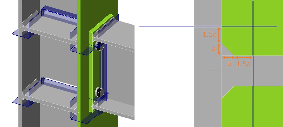
Welds in CBFEM consist of the weld element with multipoint constraints connecting the plates. The stress distribution in the weld is disrupted by the constraints and, therefore, the stresses are taken from a section located at 1.5 times the leg size from the weld toe. Three sections are created for a double-sided fillet weld. Two sections are in the same detail category, and only the more stressed one is shown. The maximum normal stress and the corresponding shear stress at the same location, as well as the maximum shear stress and the corresponding normal stress at the same location, are shown.

See also the fatigue analysis improvements in the 22.0 version.
Plates

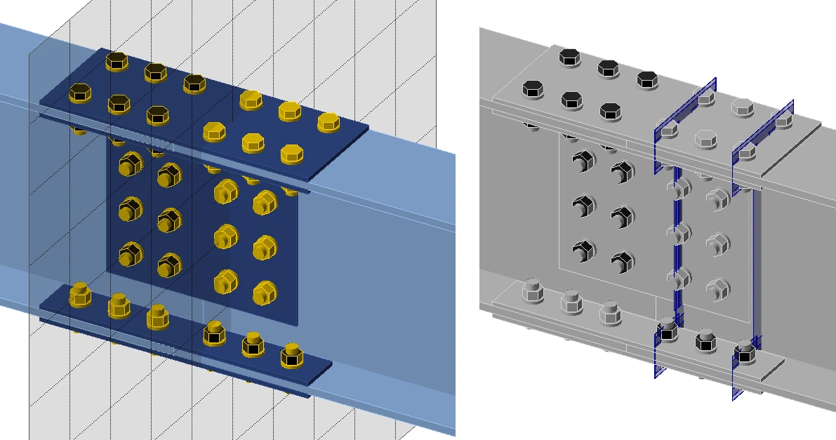
The stress in plates may be visualized by creating a user-defined section by a Workplane manufacturing operation. In the figure below, two workplaces were created to see the stresses around bolt holes. The maximum normal stress and the corresponding shear stress at the same location, as well as the maximum shear stress and the corresponding normal stress at the same location, are shown.
Related articles

IDEA StatiCa Connection – Structural design of steel connections
  • Steel
  • Connection
  • EN (Eurocode)
  • AISC (USA)
  • AS (Australia)
  • CSA (Canada)
  • IS (India)
  • GB (China)
  • HKG (Hong Kong)
  • SP 16 (Russia)
  • CBFEM
  • +11
  • Steel
  • Connection
  • EN (Eurocode)
  • AISC (USA)
  • AS (Australia)
  • CSA (Canada)
  • IS (India)
  • GB (China)
  • HKG (Hong Kong)
  • SP 16 (Russia)
  • CBFEM

Theoretical background

IDEA StatiCa Connection – Structural design of steel connections

Read more
Joints of hollow section members may undergo serious deformations while able to carry still higher loads. IDEA StatiCa - a structural design software for modeling and code-checking of steel beam connections.
  • Steel
  • Connection
  • AISC (USA)
  • CSA (Canada)
  • EN (Eurocode)
  • IS (India)
  • GB (China)
  • HKG (Hong Kong)
  • SP 16 (Russia)
  • CBFEM
  • AS (Australia)
  • +11
  • Steel
  • Connection
  • AISC (USA)
  • CSA (Canada)
  • EN (Eurocode)
  • IS (India)
  • GB (China)
  • HKG (Hong Kong)
  • SP 16 (Russia)
  • CBFEM
  • AS (Australia)

Knowledge base

Steel joints of hollow section cross-section members

Read more
How to define pre-loaded bolts
  • Steel
  • Connection
  • AISC (USA)
  • Bolts
  • Contacts
  • EN (Eurocode)
  • +6
  • Steel
  • Connection
  • AISC (USA)
  • Bolts
  • Contacts
  • EN (Eurocode)

Knowledge base

How to define preloaded bolts

Read more
How are welds modeled in IDEA StatiCa
  • Steel
  • Connection
  • CBFEM
  • Welds
  • +4
  • Steel
  • Connection
  • CBFEM
  • Welds

Knowledge base

How are welds modeled in IDEA StatiCa

Read more