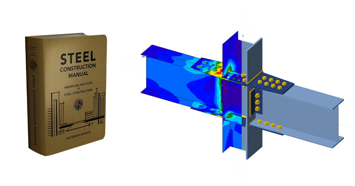


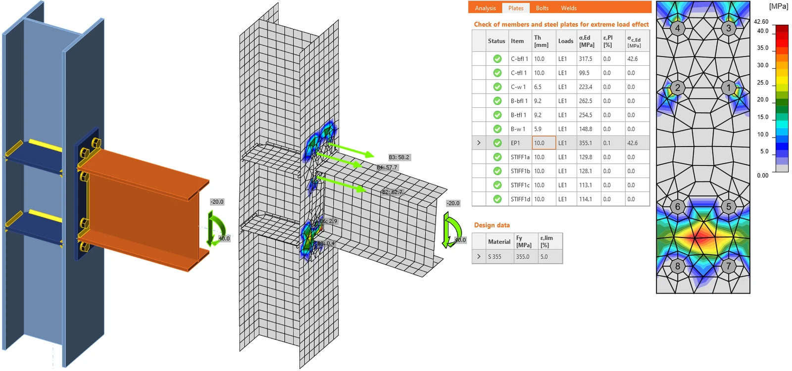
Finite element analysis in general and nonlinear finite element analysis, in particular, have been known as viable method in research for many years now. It helped to develop the code equations and provisions that engineers use. Additionally, nonlinear finite element analysis has been used extensively in practice in the US and around the world to solve engineering problems from simple to complex ones.
US codes and standards, including ACI, AISC, TMS, NDS, and others include clauses that allow the use of nonlinear finite element analysis for structural elements and connections that are not covered by the codes, which are typically complex. If the codes allow the use of this method for complex problems, then it can solve even simple problems that have assumptions that simplify the solution. Research showed limit states of members and connections design can be captured by finite element analysis. Here are some of the references listed in various sections of the AISC manual.
AISC 360 commentary indicates in various locations the possibility of using finite element analysis and nonlinear finite element such as:
- “The provisions also permit the use of computational analysis (e.g., the finite element method) to replace the Specification equations used to evaluate limit states covered by Chapters D through H, J, and K” in the Commentary section: Appendix 1, Comm 1.1 page 573, of the 16th edition of the AISC manual.
- “Any method of design that is based on inelastic analysis and satisfies the given general requirements is permitted. These methods may include the use of nonlinear finite element analyses (Crisfield, 1991; Bathe, 1995) that are based on continuum elements to design a single structural component such as a connection, or the use of second-order inelastic frame analyses (Clarke et al., 1992; McGuire et al., 2000) to design a structural system consisting of beams, columns and connections.” In Comm 1.3 16.1-582 of the 16th edition of the AISC manual.
- “When the connections to be modeled do not fall within the range of the databases, it may be possible to determine the response characteristics from tests, simple component modeling, or finite element studies (FEMA, 1995).” In B3. Commentary, page 16.1-322 of the 16th edition of the AISC manual.
- “When the design engineer encounters beams that do not contain an axis of symmetry or any other shape for which there are no provisions in the other sections of Chapter F, the stresses are to be limited by the yield stress or the elastic buckling stress. The stress distribution and/or the elastic buckling stress must be determined from principles of structural mechanics, textbooks or handbooks, such as the SSRC Guide (Ziemian, 2010), papers in journals, or finite element analyses. Alternatively, the designer can avoid the problem by selecting cross-sections from among the many choices given in the previous sections of Chapter F.” in Comm. F12 16.1-393 of the 16th edition of the AISC manual.
- “For weld lengths greater than 100 times the weld size, the effective length should be taken less than the actual length. The reduction factor, provided in Section J2.2b is the equivalent to that given in CEN (2005), which is a simplified approximation of exponential formulas developed by finite element studies and tests performed in Europe over many years.” In Comm J2. page 16.1-484 of the 16th edition of the AISC manual.
AISC Design Guide 1 Base connection design for Steel Structures third edition, contains two new appendices (Appendices C and D) to provide methods for the representation of column base connections in frame analysis and design guidance regarding their simulation through finite element analysis.
- Appendix D - Guidance for the Use of Finite Element Analysis for Base Plate Analysis and Design, Focused on Exposed Column Base Connection Details
AISC Design Guide 24 Hollow Structural Section connections, third edition cites:
- "The Commentary to AISC Specification Chapter K cites inelastic finite element (FE) analysis as a tool for design beyond the limits of applicability for experienced engineers, and this option is permitted by AISC Specification Appendix 1. Both welded and bolted connections may be designed by FE methods, with elastic analysis being sufficient for fatigue design but inelastic analysis being generally necessary to capture the ultimate limit state. Any limitations of the chosen software should always be checked to ensure that the software has the capability of properly investigating and capturing the limit state being investigated. This may involve confirmation of nonlinear analysis, failure criteria, sufficient number of nodes and elements permitted, element types in the library, and so forth." in Chapter 2.13, pg 41.
- "In this case, the FE modeling technique and chosen mesh and material parameters should be verified against some FE analyses from the research literature or from collected benchmark cases (which in turn have been validated), such as by Wald et al. (2017)." in Chapter 2.13 pg 41.
Structural engineers and connection designers can use a set of tools to get their job done - to safely, accurately, and quickly design steel connections as per AISC. IDEA StatiCa, with its unique and tested FEA solution, is part of this toolkit. Read more about the method in our Theoretical background and extensive set of verifications.