Idea Statica
  • Steel
  • Concrete
  • BIM & Workflows
  • Support & Learning
  • Pricing
  • Company
  • Steel overview
  • Connection design
  • Member design
  • Parametric design
  • Steel case studies
  • Concrete overview
  • Walls and D-regions
  • Anchoring design
  • Concrete case studies
  • BIM Overview
  • Supported integrations
  • Checkbot
  • Viewer
  • APIs
  • Support Center
  • E-learning & certification
  • Blog
  • Downloads & Licensing
  • Plans
  • Free community tool
  • Enterprise customers
  • Students & educators
  • How much will you save?
  • About us
  • Contact
  • Research & development
  • Authorized resellers
  • Meet our customers
  • Career
  • Steel
    Steel overviewConnection designMember designParametric designSteel case studies
  • Concrete
    Concrete overviewWalls and D-regionsAnchoring designConcrete case studies
  • BIM & Workflows
    BIM OverviewSupported integrationsCheckbotViewerAPIs
  • Support & Learning
    Support CenterE-learning & certificationBlogDownloads & Licensing
  • Pricing
    PlansFree community toolEnterprise customersStudents & educatorsHow much will you save?
  • Company
    About usContactResearch & developmentAuthorized resellersMeet our customersCareer
14-Day Trial
14-Day Trial
  • Steel
  • Concrete
  • BIM & Workflows
  • Support & Learning
  • Pricing
  • Company

Subscribe to our newsletter

Company

  • About us
  • Partners
  • Careers
  • Patent

Resources

  • Customer projects
  • Case studies
  • Connection Library
  • Verification books

Legal

  • EULA
  • Privacy policy
  • California Privacy
  • TOS Viewer
  • Licensing

Help

  • Contact
  • Quote request
  • Resellers
  • Downloads
FacebookInstagramLinkedInYouTube

Ā© IDEA StatiCa 2009-2026

Trusted and used worldwide by engineers, fabricators & consultants.

Support CenterKnowledge Base ArticlesCode-check of welds according to Australian standards
Advanced analysis types for your steel structures
Weld / Welds in IDEA StatiCa
Weld sizing
Check welds of welded sections
Warnings for welds and bolts connecting the same plates
Weld spreading area
Weld checks specifics as per Eurocode (EN) and Indian Standard (IS)
Welded connections analysis
Code-check of welds (EN)
Code-check of welds (AISC)
Code-check of welds according to Canadian standards
Code-check of welds according to Australian standards
Code-check of welds according to Chinese standard
Code-check of welds according to Hong Kong Code
Code-check of welds according to Indian standards
Code-check of welds according to Russian standards
Fillet welds are checked according to AS 4100 - Chapter 9.7. The strength of CJP groove welds is assumed the same as the base metal and is not checked. Structural design of welded steel connections and steel beam-to-column connections.
Connection designSteelKnowledge baseConnectionCBFEM

Code-check of welds according to Australian standards

This article is also available in
ENCZDEESFRITPTNLHUROKRPLTHTRVIZH

Fillet welds are checked according to AS 4100 - Chapter 9.6. The strength of CJP groove welds is assumed the same as the base metal and is not checked.

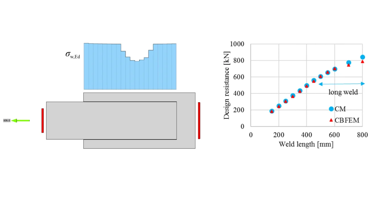
It is possible to set butt welds or fillet welds and along the full edge length, partial welds, or intermittent welds. Butt welds are assumed to have the same strength as the welded member and are not checked. In the case of fillet welds, the weld element is inserted between interpolation links connecting plates to each other. The weld element has a specified elasto-plastic material diagram to redistribute the stress along the weld length so that the long welds, multi-orientation welds or welding to unstiffened flange have similar resistance as according to hand calculation. The most stressed weld element is decisive in the weld check.

A fillet weld subject to a design force per unit length of weld, vw*, is designed according to Cl.Ā 9.6.3.10 and shall satisfy:

vwāˆ—ā‰¤Ļ•vwv_w^* \le Ļ• v_wvwāˆ—ā€‹ā‰¤Ļ•vw​

where:

  • Ļ• = 0.8 – capacity factor (Chapter 3.4) editable in Code setup
  • vw = 0.6 fuw tt – nominal capacity of a fillet weld per unit length
  • fuw – nominal tensile strength of weld metal (Table 9.6.3.10 (A))
  • tt – design throat thickness

The reduction factor, kr is assumed equal to 1 (weld shorter than 1.7Ā m).

The weld diagrams show stress according to the following formula:

σ=σ⊄2+Ļ„āŠ„2+Ļ„āˆ„2\sigma = \sqrt{ \sigma_{\perp}^2 + \tau_{\perp}^2 + \tau_{\parallel}^2 }σ=σ⊄2​+Ļ„āŠ„2​+Ļ„āˆ„2​​

Related articles

The forces in bolts, including prying forces, are determined by finite element analysis. The bolt resistances are checked by code provisions. Structural design of bolted steel connections.
  • Steel
  • Connection
  • CBFEM
  • Bolts
  • AS (Australia)
  • +5
  • Steel
  • Connection
  • CBFEM
  • Bolts
  • AS (Australia)

Knowledge base

Code-check of bolts and preloaded bolts according to Australian standards

Read more
The concrete below the base plate is simulated by Winkler subsoil with uniform stiffness, which provides the contact stresses. IDEA StatiCa - concrete design software for structural code-check of concrete constructions.
  • Steel
  • AS (Australia)
  • Connection
  • CBFEM
  • Concrete block
  • Steel-to-concrete
  • Anchoring
  • +7
  • Steel
  • AS (Australia)
  • Connection
  • CBFEM
  • Concrete block
  • Steel-to-concrete
  • Anchoring

Knowledge base

Code-check of concrete block according to Australian standards

Read more
What is the correct length of the weld?
  • Steel
  • Connection
  • EN (Eurocode)
  • Anchoring
  • Welds
  • AISC (USA)
  • +6
  • Steel
  • Connection
  • EN (Eurocode)
  • Anchoring
  • Welds
  • AISC (USA)

Knowledge base

Weld size and length

Read more
How are welds modeled in IDEA StatiCa
  • Steel
  • Connection
  • CBFEM
  • Welds
  • +4
  • Steel
  • Connection
  • CBFEM
  • Welds

Knowledge base

How are welds modeled in IDEA StatiCa

Read more