
Idea Statica
  • Steel
  • Concrete
  • BIM & Workflows
  • Support & Learning
  • Pricing
  • Company
  • Steel overview
  • Connection design
  • Member design
  • Parametric design
  • Steel case studies
  • Concrete overview
  • Walls and D-regions
  • Anchoring design
  • Concrete case studies
  • BIM Overview
  • Supported integrations
  • Checkbot
  • Viewer
  • APIs
  • Support Center
  • E-learning & certification
  • Blog
  • Downloads & Licensing
  • Plans
  • Free community tool
  • Enterprise customers
  • Students & educators
  • How much will you save?
  • About us
  • Contact
  • Research & development
  • Authorized resellers
  • Meet our customers
  • Career
  • Steel
    Steel overviewConnection designMember designParametric designSteel case studies
  • Concrete
    Concrete overviewWalls and D-regionsAnchoring designConcrete case studies
  • BIM & Workflows
    BIM OverviewSupported integrationsCheckbotViewerAPIs
  • Support & Learning
    Support CenterE-learning & certificationBlogDownloads & Licensing
  • Pricing
    PlansFree community toolEnterprise customersStudents & educatorsHow much will you save?
  • Company
    About usContactResearch & developmentAuthorized resellersMeet our customersCareer
14-Day Trial
14-Day Trial
  • Steel
  • Concrete
  • BIM & Workflows
  • Support & Learning
  • Pricing
  • Company

Subscribe to our newsletter

Company

  • About us
  • Partners
  • Careers
  • Patent

Resources

  • Customer projects
  • Case studies
  • Connection Library
  • Verification books

Legal

  • EULA
  • Privacy policy
  • California Privacy
  • TOS Viewer
  • Licensing

Help

  • Contact
  • Quote request
  • Resellers
  • Downloads
FacebookInstagramLinkedInYouTube

© IDEA StatiCa 2009-2026

Trusted and used worldwide by engineers, fabricators & consultants.

Support CenterKnowledge Base Articles2.8 Presentation of results
2.8 Presentation of results
ConcreteKnowledge baseDetail 2DACI (USA)EN (Eurocode)

2.8 Presentation of results

This article is also available in
ENCZDEESFRITPTNLHUROKRPLTHTRVIZH

Results are presented independently for concrete and for reinforcement elements. The stress and strain values in concrete are calculated at the integration points of shell elements. However, as it is not practical to present the data in such a manner, the results are presented by default in nodes, like the maximal value of compressive stress from adjacent gauss integration points in connected elements (Fig. 18). It should be noted that this representation might locally underestimate the results at compressed edges of members in a case that the finite-element size is similar to the depth of the compression zone.

Fig. 22	 Concrete finite element with integration points and nodes: presentation of the results for concrete in nodes and in finite elements.

Fig. 18 - Concrete finite element with integration points and nodes: presentation of the results for concrete in nodes and in finite elements.

The results for the reinforcement finite elements are either constant for each element (one value – e.g., for steel stresses) or linear (two values – for bond results). For auxiliary elements, such as elements of bearing plates, only deformations are presented.
Related articles

Solution for walls and details of concrete structures
  • Concrete
  • Detail 2D
  • EN (Eurocode)
  • CSFM
  • SLS
  • Wall
  • ACI (USA)
  • +7
  • Concrete
  • Detail 2D
  • EN (Eurocode)
  • CSFM
  • SLS
  • Wall
  • ACI (USA)

Verifications

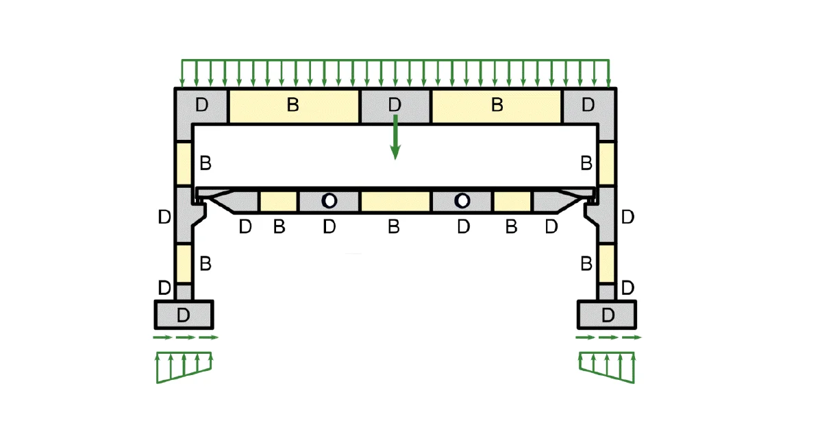
Solution for walls and details of concrete structures

Read more
Fire resistance check of concrete structures
  • Concrete
  • EN (Eurocode)
  • RCS
  • Fire resistance
  • +4
  • Concrete
  • EN (Eurocode)
  • RCS
  • Fire resistance

Webinar

Fire resistance check of concrete structures

Read more