Idea Statica
Steel
Concrete
BIM & Workflows
Support & Learning
Pricing
Company
14-Day Trial
Support CenterKnowledge BaseHow to model both side splice connection
How to model both side splice connection
Connection designSteelKnowledge baseConnectionManufacturing operations

How to model both side splice connection

This article is also available in
ENCSDEESFRITPTNLHURO

A splice connection refers to the joining of two or more steel members to create a continuous structural element. Splice connections are commonly used in applications where longer structural members are required, such as beams, columns, trusses, and girders.

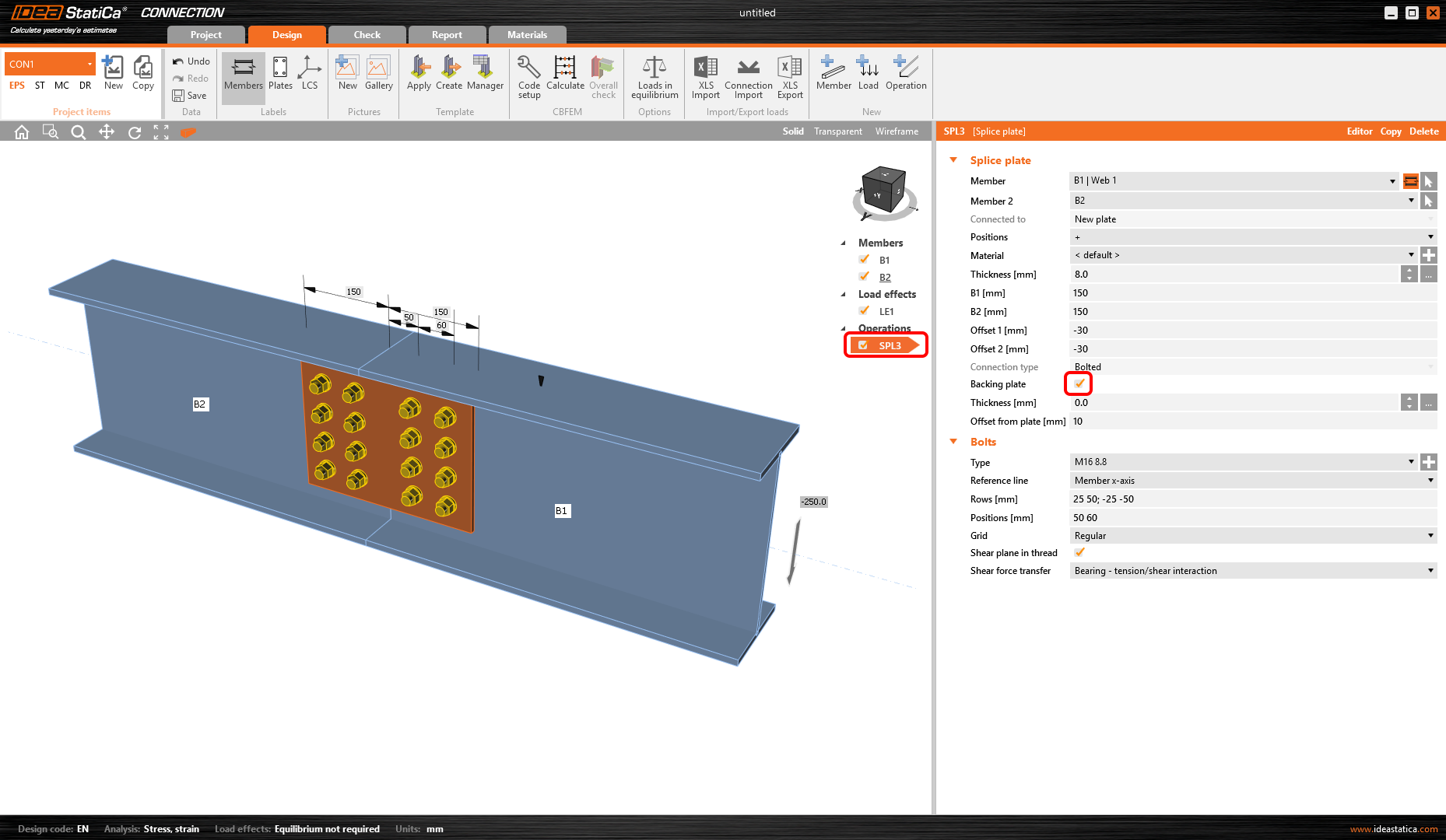
The design of two-side operations (like splices) is now easier than ever before. Add the backing plate to model everything in one operation.

Take advantage of the predefined templates:

How to model both side splice connection

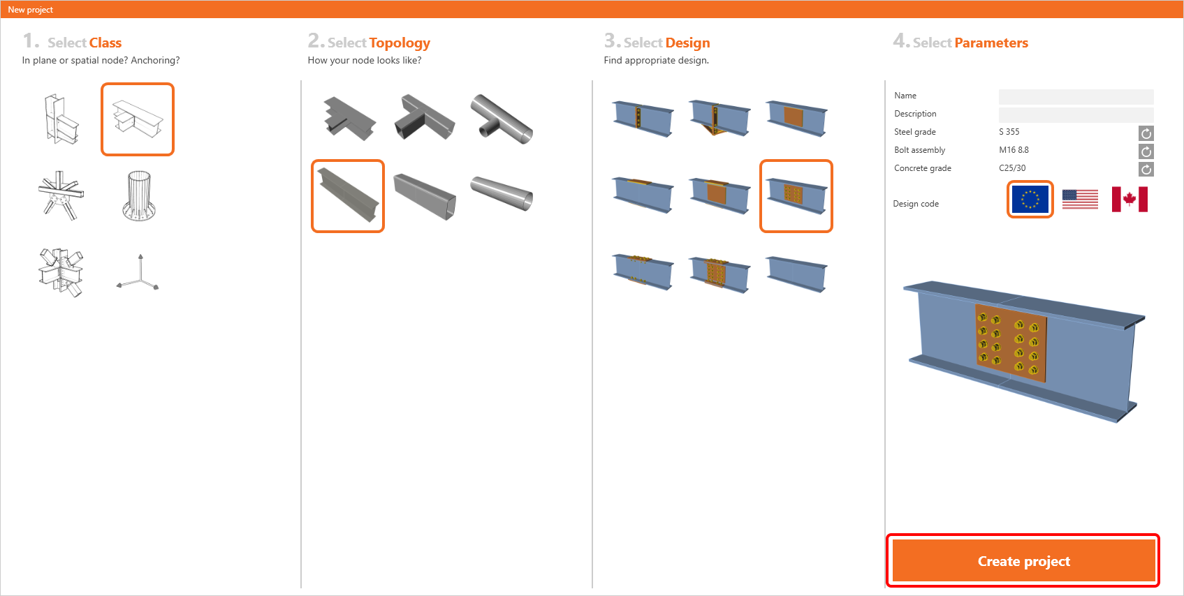
The template prepared the topology, load effects, and one manufacturing operation - just ready to run the calculation. Of course, everything can be edited and you can change the parameters of the SPL manufacturing operation including the splice and also its backing plate. 

How to model both side splice connection

Subscribe to our newsletter

Company

  • About us
  • Partnerships
  • Job openings
  • Patented technology for structural engineers

Resources

  • Customer projects
  • Case studies
  • IDEA StatiCa Connection Library
  • Concrete verifications

Legal

  • IDEA StatiCa END USER LICENSE AGREEMENT
  • Privacy policy
  • Terms of Services – IDEA StatiCa Viewer
  • Licensing

Help

  • Contact
  • Get price quote
  • IDEA StatiCa Specialists
  • Download the latest version
FacebookInstagramLinkedInYouTube

© IDEA StatiCa 2009-2026

Trusted and used worldwide by engineers, fabricators & consultants.