Connections must be designed to transform tensile force that is generated by second-order effects – column is removed and the floor acts as a membrane.
Supports
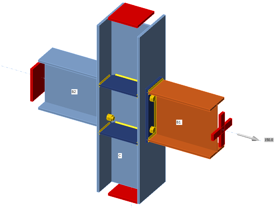
Only one member is analyzed and all other members are fixed at their ends. Only the normal force should be applied to the analyzed member, so its model type is set to N-Vy-Vz (bending moments and torsion are restricted).
Loading
Normal force acting on the analyzed member should be determined according to EN 1993-1-7, Cl. A.5.1:
For internal ties:
\[T_i=0.8(g_k+\psi q_k) s L \ge 75 \textrm{ kN} \]
For perimeter ties:
\[T_p=0.4(g_k+\psi q_k) s L \ge 75 \textrm{ kN} \]
where:
- \(g_k\) – characteristic permanent loading
- \(q_k\) – characteristic imposed loading
- \(s\) – spacing of ties
- \(L\) – span of the tie
- \(\psi\) – relevant factor in the expression for a combination of action effects for the accidental design situation (i.e. \(\psi_1\) or \(\psi_2\) in accordance with expression (6.11b) of EN 1990).
Material model and checks
According to SCI P358: Joints in steel construction: Simple Joints to Eurocode 3 – Appendix A, the partial safety factor for horizontal tying is introduced, \(\gamma_{Mu}\) with default value 1.1 editable in Code setup. This safety factor is used for plates, bolts, and welds in horizontal tying analysis.
Extreme loads and deformations are expected and the design of plates is based on the ultimate strength of plates, \(f_u\). That is why the material model for finite element analysis behaves elastically up to \(f_u / \gamma_{Mu}\). The slope of the plastic branch is Young's modulus of elasticity \(E/1000\). Check is performed for 5% plastic strain limit.
The resistances of bolts and welds are calculated with \(\gamma_{Mu}\) instead of \(\gamma_{M2}\). When using the default values of partial safety factors, the load resistances are higher by about 14 % than for the ultimate limit state.
Preloaded bolts are assumed to slip and they are checked as regular, snug-tight bolts.
References
EN 1993-1-7: Eurocode 1 – Actions on structures – Part 1-7: General actions – Accidental actions, CEN, 2006.
SCI P358: Joints in steel construction: Simple Joints to Eurocode 3