Idea Statica
  • Steel
  • Concrete
  • Support & Learning
  • Pricing
  • Company
  • Steel overview
  • Connection design
  • Member design
  • Parametric design
  • Steel case studies
  • Concrete overview
  • Walls and D-regions
  • Anchoring design
  • Concrete case studies
  • BIM Overview
  • Supported integrations
  • Checkbot
  • Viewer
  • APIs
  • Support Center
  • E-learning & certification
  • Blog
  • Downloads & Licensing
  • Plans
  • Free community tool
  • Enterprise customers
  • Students & educators
  • How much will you save?
  • About us
  • Contact
  • Research & development
  • Authorized resellers
  • Meet our customers
  • Career
  • Steel
    Steel overviewConnection designMember designParametric designSteel case studies
  • Concrete
    Concrete overviewWalls and D-regionsAnchoring designConcrete case studies
  • BIM OverviewSupported integrationsCheckbotViewerAPIs
  • Support & Learning
    Support CenterE-learning & certificationBlogDownloads & Licensing
  • Pricing
    PlansFree community toolEnterprise customersStudents & educatorsHow much will you save?
  • Company
    About usContactResearch & developmentAuthorized resellersMeet our customersCareer
14-Day Trial
14-Day Trial

Subscribe to our newsletter

Company

  • About us
  • Partners
  • Careers
  • Patent

Resources

  • Customer projects
  • Case studies
  • Connection Library
  • Verification books

Legal

  • EULA
  • Privacy policy
  • California Privacy
  • TOS Viewer
  • Licensing

Help

  • Contact
  • Quote request
  • Resellers
  • Downloads
FacebookInstagramLinkedInYouTube

© IDEA StatiCa 2009-2026

Trusted and used worldwide by engineers, fabricators & consultants.

Support CenterVerification examplesBolted End-Plate Connections Verification (EC)
Bolted End-Plate Connections Verification (EC)
SteelConnection designVerificationsConnectionEnd plate

Bolted End-Plate Connections Verification (EC)

In this verification study, a bolted beam-to-column connection using an end plate was investigated. The connection was subjected to a bending moment and comprised a large number of bolt rows.

This study investigates the assumptions of distribution of forces in bolt rows at an end-plate connection. 

EN 1993-1-8:2005, Clause 6.2.7.2(9) states:

Where the effective design tension resistance Ftx,Rd of one of the previous bolt rows x is greater than 1.9 Ft,Rd​, the effective design tension resistance Ftr,Rd for bolt row r should be reduced, if necessary, in order to ensure that:

Ftx,Rd⋅hrhxF_{tx,Rd} \cdot \frac{h_r}{h_x}Ftx,Rd​⋅hx​hr​​

where:

  • hx is the distance from bolt row x to the center of compression;
  • x  is the bolt row farthest from the center of compression that has a design tension resistance greater than 1.9 Ft,Rd.

Three cases are investigated:

  1. Resistance of each bolt row was always below the limit of 1.9â‹…Ft,Rd. Plastic force distribution is assumed in the component method.
  2. The limit of 1.9â‹…Ft,Rd was reached already in the first bolt row. Elastic force distribution is assumed in the component method.
  3. The limit of 1.9â‹…Ft,Rd was reached in the second bolt row below the beam flange. Elastic force distribution is assumed in the rows below in the component method.

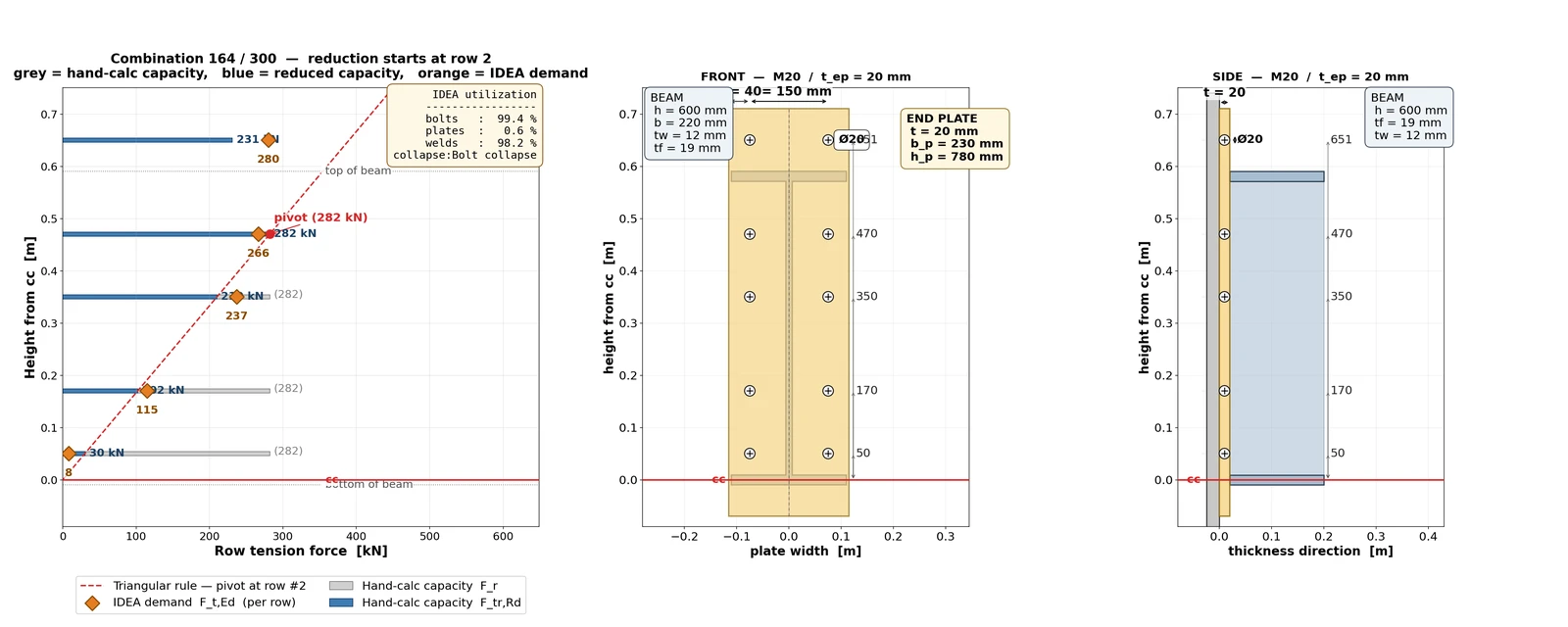
The results include a comparison of bolt forces (CBFEM) or T-stub resistances (CM) in each bolt row:
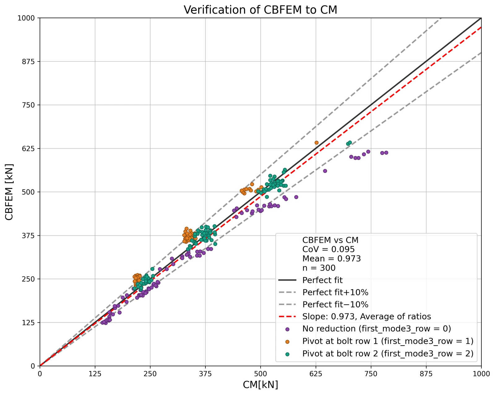
The resistances determined using the two methods, CM and CBFEM, are in close agreement:
Read the full report in the attached pdf.

The results of each case, along with the validation calculation example, are available in this zip folder:

End_plates_verification_S355.zip

Open in ViewerDownload

Attached Downloads

  • End_plates_verification_S355.pdf (PDF, 1.6 MB)